In EDUvision episode 10 season 3, we demonstrated three projects that can be used as musical instruments. Want to create your own Arduino band with your friends? Follow this tutorial and start rocking!
Can you guess what song we are playing?
Theremin
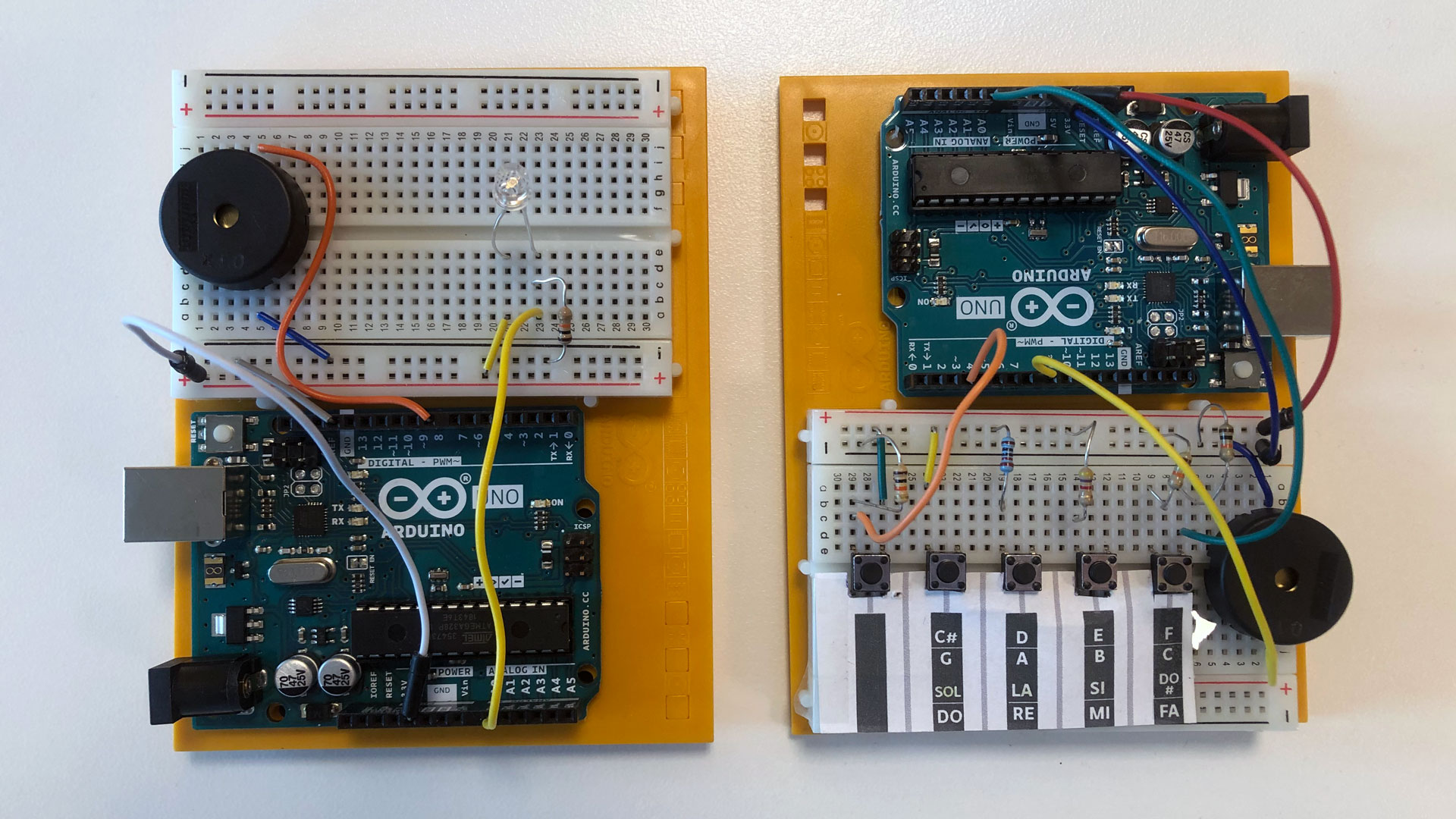
Use a piezo and a light sensor to make a light-based theremin. You can find the needed components from the Arduino Starter Kit and Arduino Student Kit. Tutorial video for Arduino Starter Kit Light Theremin project
Keyboard with Arduino UNO R3 and buttons
Use pushbuttons to create your own mini keyboard. You can find the needed components from the Arduino Starter Kit and Arduino Student Kit. Tutorial video for Arduino Starter Kit Keyboard Project
MKR IoT Carrier Instrument
Use the MKR IoT Carrier as a musical instrument! Use the touch buttons and the in-built piezo to play notes. You only need the MKR IoT Carrier and MKR WiFi 1010 board, no wiring needed.
Materials needed
Theremin
- Arduino board
- Breadboard
- Phototransistor
- 10K Ω resistor
- Piezo
- Jumper wires
Keyboard
- Arduino board
- Breadboard
- 1x 220 Ω resistor
- 1x 1K Ω resistor
- 2x 4.7 Ω resistor
- 1x 10k Ω resistor
- Jumper wires
MKR IoT Carrier Instrument
- Arduino MKR WiFi 1010
- MKR IoT Carrier
- 18650 Li-Ion 3.7 V battery (optional if you want wireless capabilities)
Wiring
Code
Theremin code
// variable to hold sensor value
int sensorValue;
// variable to calibrate low value
int sensorLow = 1023;
// variable to calibrate high value
int sensorHigh = 0;
// LED pin
const int ledPin = 13;

void setup() {
  // Make the LED pin an output and turn it on
  pinMode(ledPin, OUTPUT);
  digitalWrite(ledPin, HIGH);
  Serial.begin(9600);

  // calibrate for the first five seconds after program runs
  while (millis() < 5000) {
    // record the maximum sensor value
    sensorValue = analogRead(A0);
    if (sensorValue > sensorHigh) {
      sensorHigh = sensorValue;
    }
    // record the minimum sensor value
    if (sensorValue < sensorLow) {
      sensorLow = sensorValue;
    }
  }
  // turn the LED off, signaling the end of the calibration period
  digitalWrite(ledPin, LOW);
}

void loop() {
  //read the input from A0 and store it in a variable
  sensorValue = analogRead(A0);

  // map the sensor values to a wide range of pitches
  int pitch = map(sensorValue, sensorLow, sensorHigh, 50, 4000);
  Serial.println(pitch);

  if (pitch > 0)
  // play the tone for 20 ms on pin 8
  tone(8, pitch, 20);

  // wait for a moment
  delay(10);
}
Keyboard code
// name Arduino board pins used by the circuit
const int notePin = A0;
const int togglePin = 3;
const int buzzerPin = 8;
// declare variables
int rate = 500;
int frequency = 1000000 / (rate * 2);


// declare variables
int keyVal = 0;
int key = 0;
int switchState = 0;
int note = 0;                       // stores which note should be played
int oldNote = 0;

// an array of notes with frequencies of middle C, D, E, F, G, A, B, and high C
int notes[] = {262, 294, 330, 349, 392, 440, 494, 523};

void setup() {
  // set up pins as INPUTS or OUTPUTS
  pinMode(togglePin, INPUT);
  pinMode(buzzerPin, OUTPUT);
  // open a serial connection to the computer
  Serial.begin(9600);
}

void loop() {
  // read the inputs from the Arduino board
  keyVal = analogRead(notePin);                       // analog value of the key
  switchState = digitalRead(togglePin);
  if (keyVal > 1005) {key = 1;}
  else if (keyVal > 900) {key = 2;}
  else if (keyVal > 600) {key = 3;}
  else if (keyVal > 400) {key = 4;}
  else {key = 0;}

    // determine the note to play based on if the toggle button is up or down
  switch (switchState) {
    case 0:
     // button is not pressed so play low notes (0 through 3)
      note = key - 1;

    break;

    case 1:
     // button is pressed so play high notes (4 through 7)
      note = key + 3;
    break;
}

  // if a key is pressed, play the corresponding sound; otherwise, don't play anything
  if (key > 0) {
  tone(buzzerPin, notes[note]);
  }
  else {
   noTone(buzzerPin);
  }
  // display information only when the note changes
  if (note != oldNote) {
  }

  // display information only when the note changes
  if (note != oldNote) {
    Serial.println("toggle state : analog value : note");
    Serial.print(switchState);
    Serial.print(" : ");
    Serial.print(keyVal);
    Serial.print(" : ");
    Serial.println(note);
  }
  oldNote = note;
   }
MKR IoT Carrier Instrument code
#include <SD.h>

/*
  Melody

  Adapted for the Arduino MKR IoT Carrier

*/
#include <Arduino_MKRIoTCarrier.h>
#include "pitches.h"

MKRIoTCarrier carrier;

// notes in the melody:
int melody[] = {
  NOTE_FS3, NOTE_AS3, NOTE_C4, NOTE_F3, NOTE_G3, NOTE_B3, NOTE_C4
};
// note durations: 4 = quarter note, 8 = eighth note, etc.:
int noteDurations[] = {
  4, 8, 8, 4, 4, 4, 4, 4
};

void setup() {
  Serial.begin(9600);
  CARRIER_CASE = false;
  carrier.begin();
}

void loop() {

 carrier.Buttons.update();

  // Checks if new data are available
  if (carrier.Buttons.getTouch(TOUCH0)) {
    carrier.Buzzer.sound(melody[0]);
    delay(100);
    Serial.println("0");
  }
  else if (carrier.Buttons.getTouch(TOUCH1)) {
     carrier.Buzzer.sound(melody[1]);
     delay(100);
     Serial.println("1");
  }
 else if (carrier.Buttons.getTouch(TOUCH2)) {
    carrier.Buzzer.sound(melody[2]);
    delay(100);
    Serial.println("2");
  }
  else if (carrier.Buttons.getTouch(TOUCH3)) {
     carrier.Buzzer.sound(melody[3]);
     delay(100);
     Serial.println("3");
  }
  else if (carrier.Buttons.getTouch(TOUCH4)) {
     carrier.Buzzer.sound(melody[4]);
     delay(100);
     Serial.println("4");
  }
 else {
    carrier.Buzzer.noSound();
 }

}
Test your project
When testing the Theremin project, start by calibrating the phototransistor by moving your hand up and down. The note will be controlled by the amount of light that is hitting the phototransistor.
The keyboard project allows you to play a full octave of notes, the last note has twice the frequency of the first note. Each note is assigned to a button in the circuit. The last button in the circuit will act as a toggle button. While the button is held down, it switches the keyboard between low notes and high notes in the octave. The other four buttons work as the keys of the keyboard.
When the code is uploaded to the MKR IoT Carrier, confirm that the project is working by touching the capacitive touch buttons. You should now hear notes from the piezo.
Remember that you can edit the available notes in the code for the Keyboard and Carrier projects. This way, you can play songs of your liking by finding out which notes are included in the song!
Other useful tutorials
Rickroll Box. Inspired by the popular meme, this project plays "Never Gonna Give You Up" by Rick Astley.
Banana Piano. An octave of bananas makes a piano!