Serial to Parallel Shifting-Out with a 74HC595
At sometime or another you may run out of pins on your Arduino board and need to extend it with shift registers.
Shifting Out & the 595 chip
At sometime or another you may run out of pins on your Arduino board and need to extend it with shift registers. This example is based on the 74HC595. The datasheet refers to the 74HC595 as an "8-bit serial-in, serial or parallel-out shift register with output latches; 3-state." In other words, you can use it to control 8 outputs at a time while only taking up a few pins on your microcontroller. You can link multiple registers together to extend your output even more. (Users may also wish to search for other driver chips with "595" or "596" in their part numbers, there are many. The STP16C596 for example will drive 16 LED's and eliminates the series resistors with built-in constant current sources.)
How this all works is through something called "synchronous serial communication," i.e. you can pulse one pin up and down thereby communicating a data byte to the register bit by bit. It's by pulsing second pin, the clock pin, that you delineate between bits. This is in contrast to using the "asynchronous serial communication" of the Serial.begin() function which relies on the sender and the receiver to be set independently to an agreed upon specified data rate. Once the whole byte is transmitted to the register the HIGH or LOW messages held in each bit get parceled out to each of the individual output pins. This is the "parallel output" part, having all the pins do what you want them to do all at once.
The "serial output" part of this component comes from its extra pin which can pass the serial information received from the microcontroller out again unchanged. This means you can transmit 16 bits in a row (2 bytes) and the first 8 will flow through the first register into the second register and be expressed there. You can learn to do that from the second example.
"3 states" refers to the fact that you can set the output pins as either high, low or "high impedance." Unlike the HIGH and LOW states, you can"t set pins to their high impedance state individually. You can only set the whole chip together. This is a pretty specialized thing to do -- Think of an LED array that might need to be controlled by completely different microcontrollers depending on a specific mode setting built into your project. Neither example takes advantage of this feature and you won"t usually need to worry about getting a chip that has it.
Here is a table explaining the pin-outs adapted from the Phillip's datasheet.

| PINS 1-7, 15 | Q0 - Q7 | Output Pins |
|---|---|---|
| PIN 8 | GND | Ground, Vss |
| PIN 9 | Q7 | Serial Out |
| PIN 10 | MR | Master Reclear, active low |
| PIN 11 | SH_CP | Shift register clock pin |
| PIN 12 | ST_CP | Storage register clock pin (latch pin) |
| PIN 13 | OE | Output enable, active low |
| PIN 14 | DS | Serial data input |
| PIN 16 | Vcc | Positive supply voltage |
Example 1: One Shift Register
The first step is to extend your Arduino with one shift register.
The Circuit
1. Turning it on
Make the following connections:
GND (pin 8) to ground,
Vcc (pin 16) to 5V
OE (pin 13) to ground
MR (pin 10) to 5V
This set up makes all of the output pins active and addressable all the time. The one flaw of this set up is that you end up with the lights turning on to their last state or something arbitrary every time you first power up the circuit before the program starts to run. You can get around this by controlling the MR and OE pins from your Arduino board too, but this way will work and leave you with more open pins.

2. Connect to Arduino
DS (pin 14) to Ardunio DigitalPin 11 (blue wire)
SH_CP (pin 11) to to Ardunio DigitalPin 12 (yellow wire)
ST_CP (pin 12) to Ardunio DigitalPin 8 (green wire)
From now on those will be referred to as the dataPin, the clockPin and the latchPin respectively. Notice the 0.1"f capacitor on the latchPin, if you have some flicker when the latch pin pulses you can use a capacitor to even it out.

3. Add 8 LEDs.
In this case you should connect the cathode (short pin) of each LED to a common ground, and the anode (long pin) of each LED to its respective shift register output pin. Using the shift register to supply power like this is called sourcing current. Some shift registers can't source current, they can only do what is called sinking current. If you have one of those it means you will have to flip the direction of the LEDs, putting the anodes directly to power and the cathodes (ground pins) to the shift register outputs. You should check the your specific datasheet if you aren't using a 595 series chip. Don't forget to add a 470-ohm resistor in series to protect the LEDs from being overloaded.

Circuit Diagram

The Code
Here are three code examples. The first is just some "hello world" code that simply outputs a byte value from 0 to 255. The second program lights one LED at a time. The third cycles through an array.
595 logic table:

595 timing diagram:

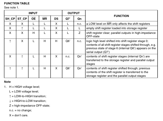
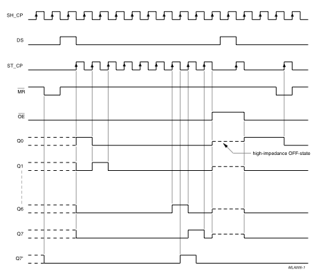
The code is based on two pieces of information in the datasheet: the timing diagram and the logic table. The logic table is what tells you that basically everything important happens on an up beat. When the clockPin goes from low to high, the shift register reads the state of the data pin. As the data gets shifted in it is saved in an internal memory register. When the latchPin goes from low to high the sent data gets moved from the shift registers aforementioned memory register into the output pins, lighting the LEDs.
Example 2
In this example you'll add a second shift register, doubling the number of output pins you have while still using the same number of pins from the Arduino.
The Circuit
1. Add a second shift register.
Starting from the previous example, you should put a second shift register on the board. It should have the same leads to power and ground.

2. Connect the 2 registers.
Two of these connections simply extend the same clock and latch signal from the Arduino to the second shift register (yellow and green wires). The blue wire is going from the serial out pin (pin 9) of the first shift register to the serial data input (pin 14) of the second register.

3. Add a second set of LEDs.
In this case I added green ones so when reading the code it is clear which byte is going to which set of LEDs

Circuit Diagram

The Code
Here again are three code samples. If you are curious, you might want to try the samples from the first example with this circuit set up just to see what happens.
Code Sample 2.1 Dual Binary Counters There is only one extra line of code compared to the first code sample from Example 1. It sends out a second byte. This forces the first shift register, the one directly attached to the Arduino, to pass the first byte sent through to the second register, lighting the green LEDs. The second byte will then show up on the red LEDs.
Code Sample 2.2 2 Byte One By One Comparing this code to the similar code from Example 1 you see that a little bit more has had to change. The blinkAll() function has been changed to the blinkAll_2Bytes() function to reflect the fact that now there are 16 LEDs to control. Also, in version 1 the pulsings of the latchPin were situated inside the subfunctions lightShiftPinA and lightShiftPinB(). Here they need to be moved back into the main loop to accommodate needing to run each subfunction twice in a row, once for the green LEDs and once for the red ones.
Code Sample 2.3 - Dual Defined Arrays Like sample 2.2, sample 2.3 also takes advantage of the new blinkAll_2bytes() function. 2.3's big difference from sample 1.3 is only that instead of just a single variable called "data" and a single array called "dataArray" you have to have a dataRED, a dataGREEN, dataArrayRED, dataArrayGREEN defined up front. This means that line
data = dataArray[j];becomes
dataRED = dataArrayRED[j];dataGREEN = dataArrayGREEN[j];
and
shiftOut(dataPin, clockPin, data);becomes
shiftOut(dataPin, clockPin, dataGREEN);shiftOut(dataPin, clockPin, dataRED);
Examples
ShftOut11
1//**************************************************************//2// Name : shiftOutCode, Hello World3// Author : Carlyn Maw,Tom Igoe, David A. Mellis4// Date : 25 Oct, 20065// Modified: 23 Mar 20106// Version : 2.07// Notes : Code for using a 74HC595 Shift Register //8// : to count from 0 to 2559//****************************************************************10//Pin connected to ST_CP of 74HC59511int latchPin = 8;12//Pin connected to SH_CP of 74HC59513int clockPin = 12;14////Pin connected to DS of 74HC59515int dataPin = 11;16void setup() {17//set pins to output so you can control the shift register18pinMode(latchPin, OUTPUT);19pinMode(clockPin, OUTPUT);20pinMode(dataPin, OUTPUT);21}22void loop() {23// count from 0 to 255 and display the number24// on the LEDs25for (int numberToDisplay = 0; numberToDisplay < 256; numberToDisplay++) {26// take the latchPin low so27// the LEDs don't change while you're sending in bits:28digitalWrite(latchPin, LOW);29// shift out the bits:30shiftOut(dataPin, clockPin, MSBFIRST, numberToDisplay);31//take the latch pin high so the LEDs will light up:32digitalWrite(latchPin, HIGH);33// pause before next value:34delay(500);35}36}ShftOut12
1/*2Shift Register Example3for 74HC595 shift register4This sketch turns reads serial input and uses it to set the pins5of a 74HC595 shift register.6Hardware:7* 74HC595 shift register attached to pins 8, 12, and 11 of the Arduino,8as detailed below.9* LEDs attached to each of the outputs of the shift register.10Created 22 May 200911Created 23 Mar 201012by Tom Igoe13*/14//Pin connected to latch pin (ST_CP) of 74HC59515const int latchPin = 8;16//Pin connected to clock pin (SH_CP) of 74HC59517const int clockPin = 12;18////Pin connected to Data in (DS) of 74HC59519const int dataPin = 11;20void setup() {21//set pins to output because they are addressed in the main loop22pinMode(latchPin, OUTPUT);23pinMode(dataPin, OUTPUT);24pinMode(clockPin, OUTPUT);25Serial.begin(9600);26Serial.println("reset");27}28void loop() {29if (Serial.available() > 0) {30// ASCII '0' through '9' characters are31// represented by the values 48 through 57.32// so if the user types a number from 0 through 9 in ASCII,33// you can subtract 48 to get the actual value:34int bitToSet = Serial.read() - 48;35// write to the shift register with the correct bit set high:36registerWrite(bitToSet, HIGH);37}38}39// This method sends bits to the shift register:40void registerWrite(int whichPin, int whichState) {41// the bits you want to send42byte bitsToSend = 0;43// turn off the output so the pins don't light up44// while you're shifting bits:45digitalWrite(latchPin, LOW);46// turn on the next highest bit in bitsToSend:47bitWrite(bitsToSend, whichPin, whichState);48// shift the bits out:49shiftOut(dataPin, clockPin, MSBFIRST, bitsToSend);50// turn on the output so the LEDs can light up:51digitalWrite(latchPin, HIGH);52}ShftOut13
1/*2
3 Shift Register Example4
5 Turning on the outputs of a 74HC595 using an array6
7 Hardware:8
9 * 74HC595 shift register10
11 * LEDs attached to each of the outputs of the shift register12
13 */14//Pin connected to ST_CP of 74HC59515int latchPin = 8;16//Pin connected to SH_CP of 74HC59517int clockPin = 12;18////Pin connected to DS of 74HC59519int dataPin = 11;20
21//holders for information you're going to pass to shifting function22byte data;23byte dataArray[10];24
25void setup() {26
27 //set pins to output because they are addressed in the main loop28
29 pinMode(latchPin, OUTPUT);30
31 Serial.begin(9600);32
33 //Binary notation as comment34
35 dataArray[0] = 0xFF; //0b1111111136
37 dataArray[1] = 0xFE; //0b1111111038
39 dataArray[2] = 0xFC; //0b1111110040
41 dataArray[3] = 0xF8; //0b1111100042
43 dataArray[4] = 0xF0; //0b1111000044
45 dataArray[5] = 0xE0; //0b1110000046
47 dataArray[6] = 0xC0; //0b1100000048
49 dataArray[7] = 0x80; //0b1000000050
51 dataArray[8] = 0x00; //0b0000000052
53 dataArray[9] = 0xE0; //0b1110000054
55 //function that blinks all the LEDs56
57 //gets passed the number of blinks and the pause time58
59 blinkAll_2Bytes(2,500);60}61
62void loop() {63
64 for (int j = 0; j < 10; j++) {65
66 //load the light sequence you want from array67
68 data = dataArray[j];69
70 //ground latchPin and hold low for as long as you are transmitting71
72 digitalWrite(latchPin, 0);73
74 //move 'em out75
76 shiftOut(dataPin, clockPin, data);77
78 //return the latch pin high to signal chip that it79
80 //no longer needs to listen for information81
82 digitalWrite(latchPin, 1);83
84 delay(300);85
86 }87}88
89// the heart of the program90void shiftOut(int myDataPin, int myClockPin, byte myDataOut) {91
92 // This shifts 8 bits out MSB first,93
94 //on the rising edge of the clock,95
96 //clock idles low97
98 //internal function setup99
100 int i=0;101
102 int pinState;103
104 pinMode(myClockPin, OUTPUT);105
106 pinMode(myDataPin, OUTPUT);107
108 //clear everything out just in case to109
110 //prepare shift register for bit shifting111
112 digitalWrite(myDataPin, 0);113
114 digitalWrite(myClockPin, 0);115
116 //for each bit in the byte myDataOut�117
118 //NOTICE THAT WE ARE COUNTING DOWN in our for loop119
120 //This means that %00000001 or "1" will go through such121
122 //that it will be pin Q0 that lights.123
124 for (i=7; i>=0; i--) {125
126 digitalWrite(myClockPin, 0);127
128 //if the value passed to myDataOut and a bitmask result129
130 // true then... so if we are at i=6 and our value is131
132 // %11010100 it would the code compares it to %01000000133
134 // and proceeds to set pinState to 1.135
136 if ( myDataOut & (1<<i) ) {137
138 pinState= 1;139
140 }141
142 else {143
144 pinState= 0;145
146 }147
148 //Sets the pin to HIGH or LOW depending on pinState149
150 digitalWrite(myDataPin, pinState);151
152 //register shifts bits on upstroke of clock pin153
154 digitalWrite(myClockPin, 1);155
156 //zero the data pin after shift to prevent bleed through157
158 digitalWrite(myDataPin, 0);159
160 }161
162 //stop shifting163
164 digitalWrite(myClockPin, 0);165}166
167//blinks the whole register based on the number of times you want to168//blink "n" and the pause between them "d"169//starts with a moment of darkness to make sure the first blink170//has its full visual effect.171void blinkAll_2Bytes(int n, int d) {172
173 digitalWrite(latchPin, 0);174
175 shiftOut(dataPin, clockPin, 0);176
177 shiftOut(dataPin, clockPin, 0);178
179 digitalWrite(latchPin, 1);180
181 delay(200);182
183 for (int x = 0; x < n; x++) {184
185 digitalWrite(latchPin, 0);186
187 shiftOut(dataPin, clockPin, 255);188
189 shiftOut(dataPin, clockPin, 255);190
191 digitalWrite(latchPin, 1);192
193 delay(d);194
195 digitalWrite(latchPin, 0);196
197 shiftOut(dataPin, clockPin, 0);198
199 shiftOut(dataPin, clockPin, 0);200
201 digitalWrite(latchPin, 1);202
203 delay(d);204
205 }206}ShftOut21
1//**************************************************************//2// Name : shiftOutCode, Dual Binary Counters //3// Author : Carlyn Maw, Tom Igoe //4// Date : 25 Oct, 2006 //5// Version : 1.0 //6// Notes : Code for using a 74HC595 Shift Register //7// : to count from 0 to 255 //8//**************************************************************//9//Pin connected to ST_CP of 74HC59510int latchPin = 8;11//Pin connected to SH_CP of 74HC59512int clockPin = 12;13////Pin connected to DS of 74HC59514int dataPin = 11;15void setup() {16//Start Serial for debugging purposes17Serial.begin(9600);18//set pins to output because they are addressed in the main loop19pinMode(latchPin, OUTPUT);20}21void loop() {22//count up routine23for (int j = 0; j < 256; j++) {24//ground latchPin and hold low for as long as you are transmitting25digitalWrite(latchPin, 0);26//count up on GREEN LEDs27shiftOut(dataPin, clockPin, j);28//count down on RED LEDs29shiftOut(dataPin, clockPin, 255-j);30//return the latch pin high to signal chip that it31//no longer needs to listen for information32digitalWrite(latchPin, 1);33delay(1000);34}35}36void shiftOut(int myDataPin, int myClockPin, byte myDataOut) {37// This shifts 8 bits out MSB first,38//on the rising edge of the clock,39//clock idles low40..//internal function setup41int i=0;42int pinState;43pinMode(myClockPin, OUTPUT);44pinMode(myDataPin, OUTPUT);45. //clear everything out just in case to46. //prepare shift register for bit shifting47digitalWrite(myDataPin, 0);48digitalWrite(myClockPin, 0);49//for each bit in the byte myDataOut�50//NOTICE THAT WE ARE COUNTING DOWN in our for loop51//This means that %00000001 or "1" will go through such52//that it will be pin Q0 that lights.53for (i=7; i>=0; i--) {54digitalWrite(myClockPin, 0);55//if the value passed to myDataOut and a bitmask result56// true then... so if we are at i=6 and our value is57// %11010100 it would the code compares it to %0100000058// and proceeds to set pinState to 1.59if ( myDataOut & (1<<i) ) {60pinState= 1;61}62else {63pinState= 0;64}65//Sets the pin to HIGH or LOW depending on pinState66digitalWrite(myDataPin, pinState);67//register shifts bits on upstroke of clock pin68digitalWrite(myClockPin, 1);69//zero the data pin after shift to prevent bleed through70digitalWrite(myDataPin, 0);71}72//stop shifting73digitalWrite(myClockPin, 0);74}ShftOut22
1//**************************************************************//2// Name : shiftOutCode, Dual One By One //3// Author : Carlyn Maw, Tom Igoe //4// Date : 25 Oct, 2006 //5// Version : 1.0 //6// Notes : Code for using a 74HC595 Shift Register //7// : to count from 0 to 255 //8//**************************************************************//9//Pin connected to ST_CP of 74HC59510int latchPin = 8;11//Pin connected to SH_CP of 74HC59512int clockPin = 12;13////Pin connected to DS of 74HC59514int dataPin = 11;15//holder for information you're going to pass to shifting function16byte data = 0;17void setup() {18//set pins to output because they are addressed in the main loop19pinMode(latchPin, OUTPUT);20}21void loop() {22//function that blinks all the LEDs23//gets passed the number of blinks and the pause time24blinkAll_2Bytes(1,500);25// light each pin one by one using a function A26for (int j = 0; j < 8; j++) {27//ground latchPin and hold low for as long as you are transmitting28digitalWrite(latchPin, 0);29//red LEDs30lightShiftPinA(7-j);31//green LEDs32lightShiftPinA(j);33//return the latch pin high to signal chip that it34//no longer needs to listen for information35digitalWrite(latchPin, 1);36delay(1000);37}38// light each pin one by one using a function A39for (int j = 0; j < 8; j++) {40//ground latchPin and hold low for as long as you are transmitting41digitalWrite(latchPin, 0);42//red LEDs43lightShiftPinB(j);44//green LEDs45lightShiftPinB(7-j);46//return the latch pin high to signal chip that it47//no longer needs to listen for information48digitalWrite(latchPin, 1);49delay(1000);50}51}52//This function uses bitwise math to move the pins up53void lightShiftPinA(int p) {54//defines a local variable55int pin;56//this is line uses a bitwise operator57//shifting a bit left using << is the same58//as multiplying the decimal number by two.59pin = 1<< p;60//move 'em out61shiftOut(dataPin, clockPin, pin);62}63//This function uses that fact that each bit in a byte64//is 2 times greater than the one before it to65//shift the bits higher66void lightShiftPinB(int p) {67//defines a local variable68int pin;69//start with the pin = 1 so that if 0 is passed to this70//function pin 0 will light.71pin = 1;72for (int x = 0; x < p; x++) {73pin = pin * 2;74}75//move 'em out76shiftOut(dataPin, clockPin, pin);77}78// the heart of the program79void shiftOut(int myDataPin, int myClockPin, byte myDataOut) {80// This shifts 8 bits out MSB first,81//on the rising edge of the clock,82//clock idles low83//internal function setup84int i=0;85int pinState;86pinMode(myClockPin, OUTPUT);87pinMode(myDataPin, OUTPUT);88//clear everything out just in case to89//prepare shift register for bit shifting90digitalWrite(myDataPin, 0);91digitalWrite(myClockPin, 0);92//for each bit in the byte myDataOut�93//NOTICE THAT WE ARE COUNTING DOWN in our for loop94//This means that %00000001 or "1" will go through such95//that it will be pin Q0 that lights.96for (i=7; i>=0; i--) {97digitalWrite(myClockPin, 0);98//if the value passed to myDataOut and a bitmask result99// true then... so if we are at i=6 and our value is100// %11010100 it would the code compares it to %01000000101// and proceeds to set pinState to 1.102if ( myDataOut & (1<<i) ) {103pinState= 1;104}105else {106pinState= 0;107}108//Sets the pin to HIGH or LOW depending on pinState109digitalWrite(myDataPin, pinState);110//register shifts bits on upstroke of clock pin111digitalWrite(myClockPin, 1);112//zero the data pin after shift to prevent bleed through113digitalWrite(myDataPin, 0);114}115//stop shifting116digitalWrite(myClockPin, 0);117}118//blinks both registers based on the number of times you want to119//blink "n" and the pause between them "d"120//starts with a moment of darkness to make sure the first blink121//has its full visual effect.122void blinkAll_2Bytes(int n, int d) {123digitalWrite(latchPin, 0);124shiftOut(dataPin, clockPin, 0);125shiftOut(dataPin, clockPin, 0);126digitalWrite(latchPin, 1);127delay(200);128for (int x = 0; x < n; x++) {129digitalWrite(latchPin, 0);130shiftOut(dataPin, clockPin, 255);131shiftOut(dataPin, clockPin, 255);132digitalWrite(latchPin, 1);133delay(d);134digitalWrite(latchPin, 0);135shiftOut(dataPin, clockPin, 0);136shiftOut(dataPin, clockPin, 0);137digitalWrite(latchPin, 1);138delay(d);139}140}ShftOut23
1//**************************************************************//2// Name : shiftOutCode, Predefined Dual Array Style //3// Author : Carlyn Maw, Tom Igoe //4// Date : 25 Oct, 2006 //5// Version : 1.0 //6// Notes : Code for using a 74HC595 Shift Register //7// : to count from 0 to 255 //8//****************************************************************9//Pin connected to ST_CP of 74HC59510int latchPin = 8;11//Pin connected to SH_CP of 74HC59512int clockPin = 12;13////Pin connected to DS of 74HC59514int dataPin = 11;15//holders for information you're going to pass to shifting function16byte dataRED;17byte dataGREEN;18byte dataArrayRED[10];19byte dataArrayGREEN[10];20void setup() {21//set pins to output because they are addressed in the main loop22pinMode(latchPin, OUTPUT);23Serial.begin(9600);24//Arduino doesn't seem to have a way to write binary straight into the code25//so these values are in HEX. Decimal would have been fine, too.26dataArrayRED[0] = 0xFF; //1111111127dataArrayRED[1] = 0xFE; //1111111028dataArrayRED[2] = 0xFC; //1111110029dataArrayRED[3] = 0xF8; //1111100030dataArrayRED[4] = 0xF0; //1111000031dataArrayRED[5] = 0xE0; //1110000032dataArrayRED[6] = 0xC0; //1100000033dataArrayRED[7] = 0x80; //1000000034dataArrayRED[8] = 0x00; //0000000035dataArrayRED[9] = 0xE0; //1110000036//Arduino doesn't seem to have a way to write binary straight into the code37//so these values are in HEX. Decimal would have been fine, too.38dataArrayGREEN[0] = 0xFF; //1111111139dataArrayGREEN[1] = 0x7F; //0111111140dataArrayGREEN[2] = 0x3F; //0011111141dataArrayGREEN[3] = 0x1F; //0001111142dataArrayGREEN[4] = 0x0F; //0000111143dataArrayGREEN[5] = 0x07; //0000011144dataArrayGREEN[6] = 0x03; //0000001145dataArrayGREEN[7] = 0x01; //0000000146dataArrayGREEN[8] = 0x00; //0000000047dataArrayGREEN[9] = 0x07; //0000011148//function that blinks all the LEDs49//gets passed the number of blinks and the pause time50blinkAll_2Bytes(2,500);51}52void loop() {53for (int j = 0; j < 10; j++) {54//load the light sequence you want from array55dataRED = dataArrayRED[j];56dataGREEN = dataArrayGREEN[j];57//ground latchPin and hold low for as long as you are transmitting58digitalWrite(latchPin, 0);59//move 'em out60shiftOut(dataPin, clockPin, dataGREEN);61shiftOut(dataPin, clockPin, dataRED);62//return the latch pin high to signal chip that it63//no longer needs to listen for information64digitalWrite(latchPin, 1);65delay(300);66}67}68// the heart of the program69void shiftOut(int myDataPin, int myClockPin, byte myDataOut) {70// This shifts 8 bits out MSB first,71//on the rising edge of the clock,72//clock idles low73//internal function setup74int i=0;75int pinState;76pinMode(myClockPin, OUTPUT);77pinMode(myDataPin, OUTPUT);78//clear everything out just in case to79//prepare shift register for bit shifting80digitalWrite(myDataPin, 0);81digitalWrite(myClockPin, 0);82//for each bit in the byte myDataOut�83//NOTICE THAT WE ARE COUNTING DOWN in our for loop84//This means that %00000001 or "1" will go through such85//that it will be pin Q0 that lights.86for (i=7; i>=0; i--) {87digitalWrite(myClockPin, 0);88//if the value passed to myDataOut and a bitmask result89// true then... so if we are at i=6 and our value is90// %11010100 it would the code compares it to %0100000091// and proceeds to set pinState to 1.92if ( myDataOut & (1<<i) ) {93pinState= 1;94}95else {96pinState= 0;97}98//Sets the pin to HIGH or LOW depending on pinState99digitalWrite(myDataPin, pinState);100//register shifts bits on upstroke of clock pin101digitalWrite(myClockPin, 1);102//zero the data pin after shift to prevent bleed through103digitalWrite(myDataPin, 0);104}105//stop shifting106digitalWrite(myClockPin, 0);107}108//blinks the whole register based on the number of times you want to109//blink "n" and the pause between them "d"110//starts with a moment of darkness to make sure the first blink111//has its full visual effect.112void blinkAll_2Bytes(int n, int d) {113digitalWrite(latchPin, 0);114shiftOut(dataPin, clockPin, 0);115shiftOut(dataPin, clockPin, 0);116digitalWrite(latchPin, 1);117delay(200);118for (int x = 0; x < n; x++) {119digitalWrite(latchPin, 0);120shiftOut(dataPin, clockPin, 255);121shiftOut(dataPin, clockPin, 255);122digitalWrite(latchPin, 1);123delay(d);124digitalWrite(latchPin, 0);125shiftOut(dataPin, clockPin, 0);126shiftOut(dataPin, clockPin, 0);127digitalWrite(latchPin, 1);128delay(d);129}130}Suggest changes
The content on docs.arduino.cc is facilitated through a public GitHub repository. If you see anything wrong, you can edit this page here.
License
The Arduino documentation is licensed under the Creative Commons Attribution-Share Alike 4.0 license.