Getting Started with the Arduino MKR Vidor 4000
The Arduino MKR Vidor 4000 is a new kind of development board which combines the high performance and flexibility of an FPGA with the Arduino's ease-of-use in a small form factor that is the distinctive trait of the MKR family of boards. It contains the Microchip SAMD21 micro controller and a Cyclone 10 FPGA.
This board hosts a number of features: onboard 8 Mbyte SDRAM, 2 Mbyte QSPI Flash (1MB for user applications), Micro HDMI connector, MIPI camera connector, Wi-Fi & Bluetooth® Low Energy powered by U-BLOX NINA W102 module, the classic MKR interface on which all pins are driven both by SAMD21 and FPGA and a MiniPCI Express connector with up to 25 user programmable pins.
The FPGA contains 16K Logic Elements, 504Kbit of embedded RAM and 56 18x18 bit HW multipliers for high-speed DSP; Each pin can toggle at over 150 MHz and can be configured for functions such as UARTs, (Q)SPI, high res/ high freq PWM, quadrature encoder, I2C, I2S, Sigma Delta DAC, etc. On board FPGA can be also used for high-speed DSP operations for audio and video processing.
The Arduino MKR Vidor 4000 is programmed using the Arduino Software (IDE), our Integrated Development Environment common to all our boards and running both online and offline. For more information on how to get started with the Arduino Software visit the Getting Started page.
Use your Arduino MKR Vidor 4000 on the Arduino Web IDE

All Arduino boards, including this one, work out-of-the-box on the Arduino Web Editor, you only need to install Arduino Create Agent to get started.
The Arduino Web Editor is hosted online, therefore it will always be up-to-date with the latest features and support for all boards. Follow this simple guide to start coding on the browser and upload your sketches onto your board.
Use your Arduino MKR Vidor 4000 on the Arduino Desktop IDE
If you want to program your MKR Vidor 4000 while offline you need to install the Arduino Desktop IDE and add the Atmel SAMD Core for Vidor to it. This simple procedure is done selecting Tools menu, then Boards and last Boards Manager, as documented in the Arduino Boards Manager page.
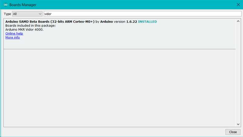
Here you can search Vidor to find the beta SAMD21 core for the board. Click on its box and click on the install button. On the bottom bar of the window you can follow the download and install procedure, including the installation of the proper driver, needed by the operating system to use the board. For more information about cores, see the guide on installing additional Arduino cores.
Now that the SAMD beta Core is installed, you can connect the board to the computer using a standard USB cable. The very first time your computer may go through the new hardware installation process.
Drivers
On Windows, drivers are needed to allow the board communication. These drivers will be installed automatically when adding the core.
On MacOS and Linux no driver is needed.
Select your board type and port
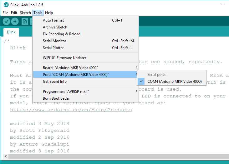
From Tools select the Board Arduino MKR Vidor 4000
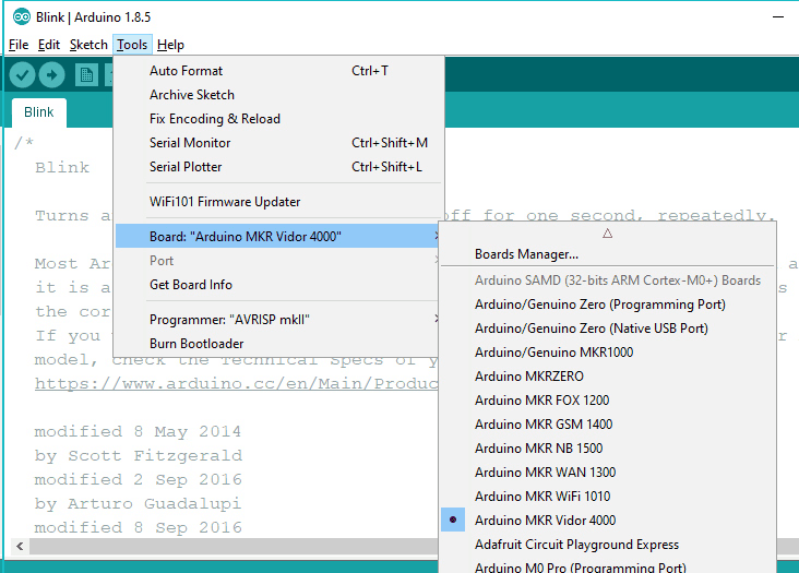
and then the Port that is labeled with the same name.
Open your first sketch
Go to File on the Arduino Software (IDE) and open the Examples tree; select 01. Basic and then Blink
This sketch just flashes the built in LED connected to Digital pin LED_BUILTIN at one second pace for on and off, but it is very useful to practice the loading of a sketch into the Arduino Software (IDE) and the Upload to the connected board.
Upload the program
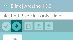
Press the second round icon from left on the top bar of the Arduino Software (IDE) or press Ctrl+U or select the menu Sketch and then Upload. Please note that the time required to load the sketch and the FPGA bitstream might be more than 30 seconds. If you want to get more information about the upload process, you may activate in the preferences the show verbose output during: option for upload.
The sketch will be compiled and then uploaded. After a few seconds the bottom bar should show Done Uploading.
You have successfully set up your MKR Vidor 4000 board and uploaded your first sketch. You are ready to move on with our tutorials and projects: choose your next destination below.
Tutorials
Now that you have set up and programmed your MKR Vidor 4000 board, you may find inspiration in our Project Hub tutorial platform.
Here a list of tutorials that will help you in making very cool things!
Learn the basics of FPGA programming
Adding more Serial interfaces to SAMD microcontrollers
More examples on the following library pages:
Scheduler - Manage multiple non-blocking tasks.
AudioFrequencyMeter - Sample an audio signal and get its frequency back
I2S - To connect digital audio devices together
Please Read
In this section we have collected some information that is worth reading to use your MKR Vidor 4000 board properly. Some behaviors differ from the Uno board and if you come from a former experience with that board, it is worth spending a few minutes reading through these notes. If this is your first board, we suggest you have a look at them anyway.
Operating Voltage
The microcontroller on the MKR Vidor 4000 runs at 3.3V. Applying more than 3.3V on any pin will damage the board. The VIN pin may be used to power the board but the voltage supplied must be 5V.
Board layout
This board uses the MKR family form factor and pinout on the standard analog and digital pins, allowing the usage of shields and accessories designed for the other MKR boards. It has a host of new features that are available through a set of new components and connectors as highlighted in the image below.
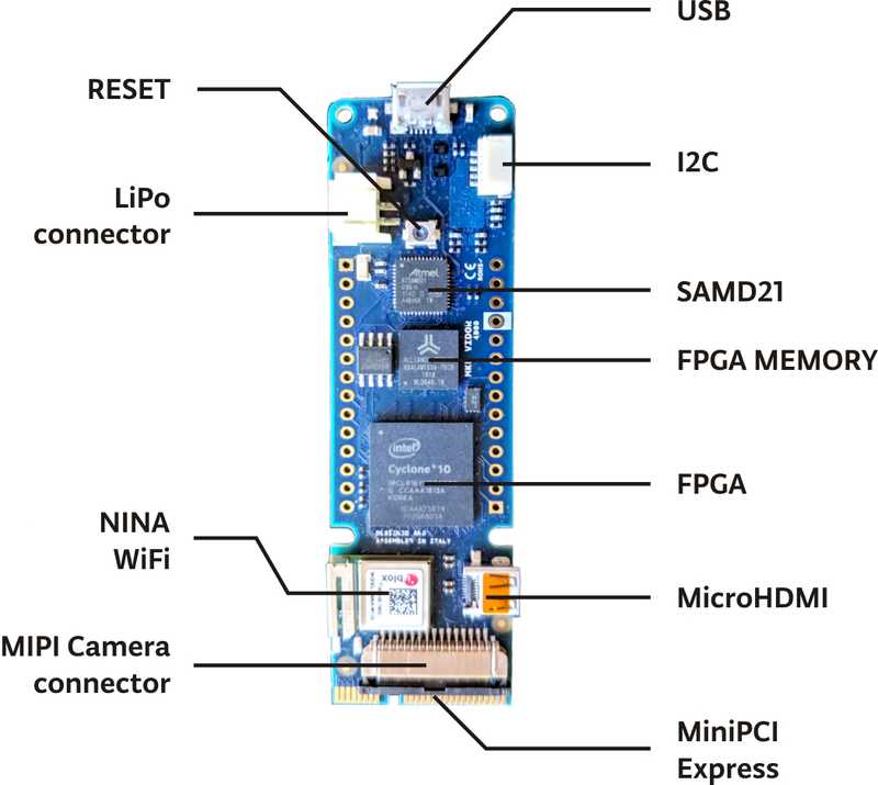
USB -
On top of the board you find a standard microUSB port, directly connected to the SAMD microcontroller. This port is seen by the host computer as a Virtual Comm Port and it cn be used to send and receive messages with the usual Serial() function and the Serial Monitor of the Arduino Software (IDE).
On the left side of the USB connector you find the BUILTIN_LED that is red; on the right side a green LED lits up when power is applied to the board. This LED won't light up when the board is powered by the LiPo battey.
LiPo Connector - This is the standard JST two poles connector for LiPo batteries. The Arduino MKR Vidor 4000 is able to run on a 3.3V battery and has been designed to support capacities of at least 500 mAh. When the board is connected to USB, it will charge automatically the LiPo battery. Charging time will depend on the battery capacity. The chip used to control the charging process is smart and it communicates with the SAMD microcontroller. In the future you will be able to manage the charging parameters and optimize capacity and charging times. Currently the charger sources 100mA.
I2C - The five pole connector on top right is our ESLOV cnnector. It is an I2C port with an added interrupt signal. From top to bottom you have: 1 - VCC (3.3V) 2 - Wake 3 - SCL 4 - SDA 5 - GND
Please note that this interface uses 3.3V levels and works with I2C devices that support 3.3V. 5V devices need level shifting circuitry.
microHDMI - This is a standard video port that allows you to connect a monitor. If you connect a MIPI Camera to the board, the output of this port is the image captured by the camera when you load the VidorGraphics library and the streming camera sketch.
miniPCI-express connector - the board has this type of connector because the female is widely available and also allows easy soldering on PCB. On this connector we have routed the pins of the FPGA that are not used elsewhere, plus some power supply and the D+ and D- of SAMD USB port. When the USB is used on this connector, it can't be used from the top USB port.
MIPI Camera Connector - the Arduino MKR Vidor 4000 is designed to drive an Omnivision OV5647 camera. The MIPI camera connector is a standard format that you find on several commercial products. This type of connector allows the easy insertion of the flat cable that is locked pressing the black slider towards the connector. To unlock the cable, you need to pull away the black slider from the connector on both sides. Never pull the flat connector cable with the slider in the lock position.
Hardware notes - This board is densely populated and it has a current consumption that depends on the complexity of the tasks performed. The FPGA can do from very light tasks to heavy computational processes, varying a lot the heat generated. Our design allows a wide range of LiPo battery capacities and you can choose the right one for your needs.
NINA-W102 WiFi
The WiFi antenna built-in in the u-blox NINA-W102 module is made for embedded products and should NOT be touched. Applying pressure or force on it could cause damage. Its position should already offer some protection, but you need to be careful when you plug and unplug shields because any upward pull force applied to the metallic antenna could detach it.
MKR pins and the FPGA
If you look at the board from below, you will find the familiar A0-A6, D0-D13 and powr labels. This is the standard MKR family layout and it is also what you expect from this board as a MKR family member. What makes the Arduino MKR Vidor 4000 special is the fact that these pins are also routed through the FPGA. Any of the A and D pins can therefore become something highly specialized as an SPI, I2C or serial communication port, a pin capable of some DSP function or something that has to be invented yet. This is the flexibility of the FPGA technology, where it is the code that creates a function inside the FPGA and the function is connected to another block or to a pin as an input or as an output. Developing this requires some in depth knowledge and programming skills, but there are tools made for this and we are pretty sure that some of our users will engage in many challenges to develop their own functions. In the meantime we have prepared an array of functionalities that address some frequent needs in the fields of application of the Arduino boards.
These functionalities are loaded as libraries that make some new APIs available together with the objects that will behave according to the functions. To keep things simple, usually the objects come preconfigured to work through specific pins. Each Vidor library will be documented with such pin maps, allowing you to chose the right object for your wiring needs.
We have prepared a basic set of FPGA based functionalities, grouped into two main libraries: VidorIPeripherals and VidorGraphics. You may download them using the usual procedure through the Library Manager with the vidor keyword in the search field.
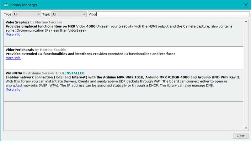
The first library is about communications and Input/output with UART, SPI, I2C, Encoders, PWM and Neopixels. The second library brings the graphics capabilities of the well known AdafruitGFX library to the HDMI video output. Full details, documentation and examples are available in the libraries references.
If you wish to get more information about the way our FPGA is programmed, here are some tutorials:
Get started in the direct programming of the FPGA on the board
How to Program the Arduino MKR Vidor 4000's FPGA with Quartus IDE
See Also
Enable Camera - Enables the video stream from a camera to an HDMI monitor
Draw Logo - Draw the Arduino Logo on an HDMI monitor
QR Recognition - The QR library allows you to recognize QR code markers and data
Encoder - Manage easily quadrature encoders and never lose an impulse
For more details on the Arduino MKR Vidor 4000, see the product page.
The text of the Arduino getting started guide is licensed under a Creative Commons Attribution-ShareAlike 3.0 License. Code samples in the guide are released into the public domain.