MKR WiFi 1010 Bluetooth® Low Energy
Bluetooth® Low Energy, referred to as BLE, separates itself from what is now known as “Bluetooth® Classic” by being optimized to use low power with low data rates. There are two different types of Bluetooth® devices: central or peripheral. A central Bluetooth® device is designed to read data from peripheral devices, and the peripheral devices are, well, designed to do the opposite. Peripheral devices continuously post data for other devices to read, and it is precisely that we will be focusing on today.
This tutorial is a great starting point for any maker interested in creating their own Bluetooth® projects.
Service & characteristics
A service can be made up of different data measurements. For example, if we have a device that measures wind speed, temperature and humidity, we can set up a service that is called “Weather Data”. Let’s say the device also records battery level and energy consumption, we can set up a service that is called “Energy information”. These services can then be subscribed to by central Bluetooth® devices.
Characteristics are components of the service we mentioned above. For example, the temperature or battery level are both characteristics, which records data and updates continuously.
Unique Universal Identifier (UUID)
When we read data from a service, it is important to know what type of data we are reading. For this, we use UUIDs, who basically gives a name to the characteristics. For example, if we are recording temperature, we want to label that characteristic as temperature, and to do that, we have to find the UUID, which in this case is “2A6E”. When we are connecting to the device, this service will then appear as “temperature”. This is very useful when tracking multiple values.
If you want to read more about UUIDs, services, and characteristics, check the links below:
Hardware needed
- Arduino MKR WiFi 1010
- Micro USB cable
- LED
- 220 ohm resistor
- Breadboard
- Jumper wires
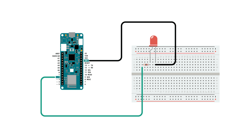
Circuit
Follow the wiring diagram below to connect the LED to the MKR WiFi 1010 board.
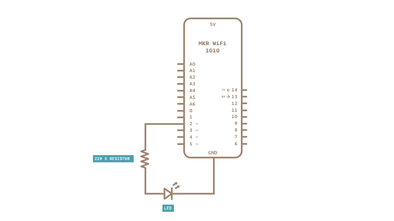
Schematic
Follow the wiring diagram below to connect the LED to the MKR WiFi 1010 board.
Software needed
- Arduino IDE (offline and online versions available)
- Arduino SAMD core installed (for offline editor only)
- ArduinoBLE library (explained later in this tutorial)
Using the offline editor
If you are using the offline editor, make sure you have installed the core needed for the MKR WiFi 1010. If you do not have it, please visit our getting started page for this board. We will also need to install the ArduinoBLE library, following the instructions below:
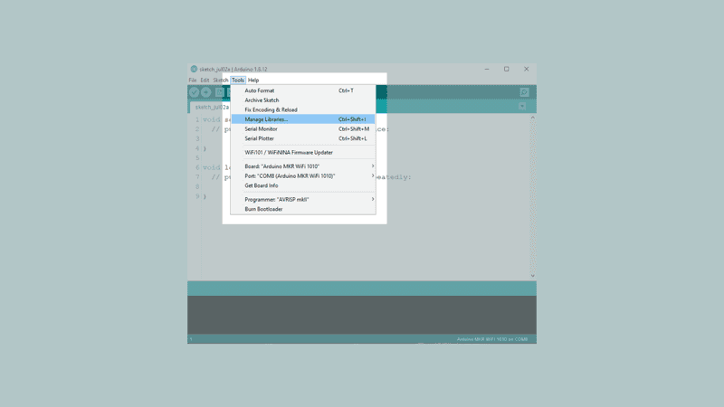
In the editor, navigate to Tools > Manage Libraries.
Then, search for ArduinoBLE Click the install button. After it is installed, it should look like the following image:
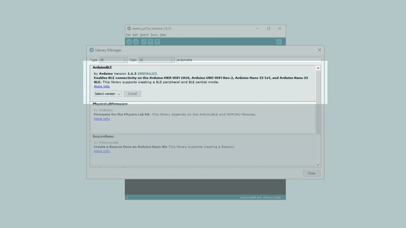
It is recommended to re-start the editor after installing a library.
Using the online editor

All Arduino boards, including this one, work out-of-the-box on the Arduino Web Editor, you only need to install Arduino Create Agent to get started.
The Arduino Web Editor is hosted online, therefore it will always be up-to-date with the latest features and support for all boards. Follow this simple guide to start coding on the browser and upload your sketches onto your board.
Let's start
The goal with this tutorial is to be able to access our MKR WiFi 1010 board via Bluetooth®, and control an LED onboard it. We will also retrieve the latest reading from an analog pin. We will then use UUIDs from the official Bluetooth® page, that are compliant with GATT (Generic Attribute Profile). This way, when we access our device later, the service and characteristics can be recognized!
We will go through the following steps in order to create our sketch:
- Create a new service
- Create an LED characteristic
- Create an analog pin characteristic
- Set the name for our device
- Start advertising the device
- Create a conditional that works only if an external device is connect (smartphone).
- Create a conditional that turns on an LED over Bluetooth®
- Read an analog pin over Bluetooth®
In the next section, we will create a sketch that can include the above steps.
Code explanation
NOTE: This section is optional, you can find the complete code further down this tutorial.
First, we need to include the ArduinoBLE library, and create a new service. We will name the service "180A" which is translated to "Device Information". We will then created two characteristics, one for the LED, and one for the analog pin. The name "2A57" is translated to "Digital Output" and "2A58 is translated to "Analog".
#include <ArduinoBLE.h
BLEService newService("180A"); // creating the service

BLEUnsignedCharCharacteristic randomReading("2A58", BLERead | BLENotify); // creating the Analog Value characteristic
BLEByteCharacteristic switchChar("2A57", BLERead | BLEWrite); // creating the LED characteristic

const int ledPin = 2;
long previousMillis = 0;
In the setup(), we will start by initializing serial communication, define both the in-built LED and the LED we connected to pin 2. We then initialize the ArduinoBLE library.
We then set the name for our device, using the command BLE.setLocalName("MKR WiFi 1010");, then add the characteristics we created earlier to the service created earlier, newService. After they have been added, we will also add the service, using the command BLE.addService(newService);.
The final things we will do is to set the starting value of 0 for both characteristics. This is mostly important for the LED, since 0 means it will be OFF from the start.
The setup is finished by using the command BLE.advertise();, which makes it visible for other devices to connect to.
void setup() {
Serial.begin(9600); // initialize serial communication
while (!Serial); //starts the program if we open the serial monitor.
pinMode(LED_BUILTIN, OUTPUT); // initialize the built-in LED pin to indicate when a central is connected
pinMode(ledPin, OUTPUT); // initialize the built-in LED pin to indicate when a central is connected
//initialize ArduinoBLE library
if (!BLE.begin()) {
Serial.println("starting Bluetooth® Low Energy failed!");
while (1);
}
BLE.setLocalName("MKR WiFi 1010"); //Setting a name that will appear when scanning for Bluetooth® devices
BLE.setAdvertisedService(newService);
newService.addCharacteristic(switchChar); //add characteristics to a service
newService.addCharacteristic(randomReading);
BLE.addService(newService); // adding the service
switchChar.writeValue(0); //set initial value for characteristics
randomReading.writeValue(0);
BLE.advertise(); //start advertising the service
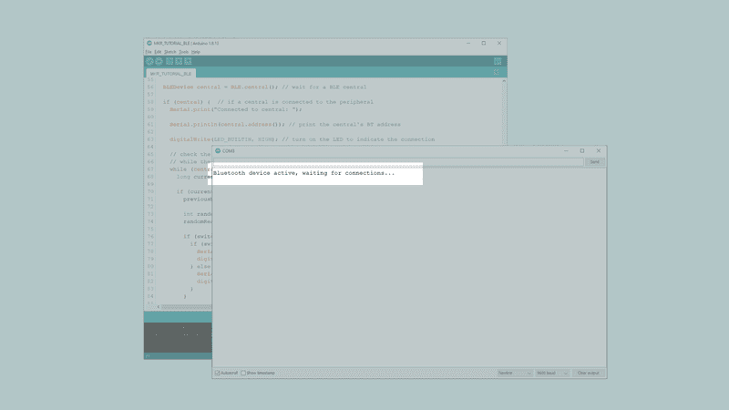
Serial.println("Bluetooth® device active, waiting for connections...");
}In the loop() we will use the command BLEDevice central = BLE.central(); to start waiting for a connection. When a device connects, the address of the connecting device (the central) will be printed in the Serial Monitor, and the in-built LED will turn ON.
After this, we use a while loop that only runs as long as a device is connected. Here, we do a reading of Analog pin 1, which will record random values between 0 and 1023. We then use a conditional to check if there's an incoming value: if any value other than 0 comes in, the LED turns ON, but if a 0 comes in, it turns it OFF.
If our device (smartphone) disconnects, we exit while loop. Once it exits, it turns off the in-built LED and prints the message "Disconnected from central" in the Serial Monitor.
void loop() {

  BLEDevice central = BLE.central(); // wait for a Bluetooth® Low Energy central

  if (central) {  // if a central is connected to the peripheral
    Serial.print("Connected to central: ");

    Serial.println(central.address()); // print the central's BT address

    digitalWrite(LED_BUILTIN, HIGH); // turn on the LED to indicate the connection


    while (central.connected()) { // while the central is connected:
      long currentMillis = millis();

      if (currentMillis - previousMillis >= 200) {
        previousMillis = currentMillis;

        int randomValue = analogRead(A1);
        randomReading.writeValue(randomValue);

        if (switchChar.written()) {
          if (switchChar.value()) {   // any value other than 0
            Serial.println("LED on");
            digitalWrite(ledPin, HIGH);         // will turn the LED on
          } else {                              // a 0 value
            Serial.println(F("LED off"));
            digitalWrite(ledPin, LOW);          // will turn the LED off
          }
        }

      }
    }

    digitalWrite(LED_BUILTIN, LOW); // when the central disconnects, turn off the LED
    Serial.print("Disconnected from central: ");
    Serial.println(central.address());
  }
}
Complete code
If you choose to skip the code building section, the complete code can be found below:
Upload sketch and testing the program
Once we are finished with the coding, we can upload the sketch to the board. Once it has been successfully uploaded, open the Serial Monitor. In the Serial Monitor, the text "Bluetooth® device active, waiting for connections...".
We can now discover our MKR WiFi 1010 board in the list of available Bluetooth® devices. To access the service and characteristic we recommend using the LightBlue application. Follow this link for iPhones or this link for Android phones.
Once we have the app open, follow the below image for instructions:
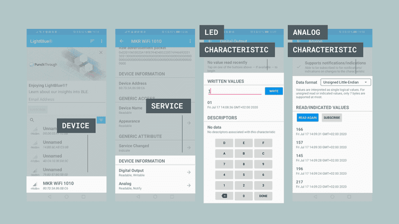
To control the LED, we simply need to write any other value than 0 to turn it on, and 0 to turn it off. This is inside the "Digital Output" characteristic, which is located under "Device Information". We can also go into the "Analog" characteristic, where we need to change the data format to "Unsigned Little-Endian", and click the "Read Again" button. Once we click the button, we will retrieve the latest value.
Troubleshoot
If the code is not working, there are some common issues we can troubleshoot:
- We haven't updated the latest firmware for the board.
- We haven't installed the core required for the board.
- We haven't installed the ArduinoBLE library.
- We haven't opened the Serial Monitor to initialize the program.
- The device you are using to connect has Bluetooth® turned off.
Conclusion
In this tutorial we have created a basic Bluetooth® peripheral device. We learned how to create services and characteristics, and how to use UUIDs from the official Bluetooth® documentation. In this tutorial, we did two practical things: turning an LED, ON and OFF, and reading a value from an analog pin. You can now start experimenting with this code, and create your own amazing Bluetooth® applications!
Now that you have learned a little bit how to use the ArduinoBLE library, you can try out some of our other tutorials for the MKR WiFi 1010 board. You can also check out the ArduinoBLE library for more examples and inspiration for creating Bluetooth® projects!
More tutorials
You can find more tutorials for this board in the MKR WiFi 1010 getting started page.
Author: Karl Söderby Reviewed by: Simone [19.07.2020] Last revision: 26.06.2020