The Arduino Boot-Cloner
What is it? Why?
The boot-cloner is a program compiled and burnt with the Arduino IDE, that copies part of it's flash memory onto another microcontroller. The bootloader can be written to a new microcontroller by the Arduino, instead of burning the bootloader onto new ATmega8's with a separate device.
Download Project and Schematic
If you're like me, then you need more than one microcontroller, so you can put the IC into a circuit and leave it there permanently. Unfortunately, burning multiple bootloaders can be a very involved, time consuming process. The cloner will help you get dozens of new ATmega8's ready to use, in seconds. The program gives you access to an implementation of the ISP protocol and declaring and using tables stored in program flash, which don't occupy ram.
Requirements
- You need a functioning Arduino that you can already write programs to. If you don't have at least one ATmega8 with a bootloader on it, you'll need to burn it using a separate device, like the parallel port burner.
- momentary push button and pull-up resistor 1K ~ 10K Ohms
- three leds and current limiting resistors appropriate for the voltage of the device. If you're working from the Arduino, you've got 5V which means 220 Ohm resistors for 20mA. If you build a 2.4V battery powered device, use lower resistors to get 20mA. (Voltage divided by current tells you resistance, so 2.4/.02=12 Ohms, 10 approx)
- two ceramic disc capacitors of 10pF (with no polarity) and a 2 to 16MHz crystal oscillator for the target microcontroller. Don't use less than 1MHz; the speed of this crystal determines the maximum rate you can issue commands and send data to the target IC, with ISP. 16MHz was convenient for me, but use whatever you've got on hand.
Pictures
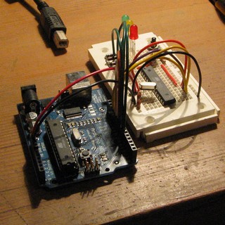

More Pictures
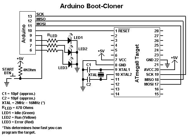
Schematic
Notes:
- Connect GND on the Arduino to pins 8 and 22 and +5V to pins 7 and 20 on the target microcontroller.
- Make sure you have the notch on the target ATmega8 facing up. I can't tell you how many times I've accidentally tried wiring the microcontroller upside-down. The good news is doing that doesn't seem to hurt anything.
Inner Workings
In-System Programming (ISP) is a protocol developed by Atmel to be used as the primary means of programming their microcontrollers. The three wire serial protocol can be used to write the fuse bits, program memory and eeprom. It's a bit of a language by itself, and varys slightly from one microcontroller to another - mostly by chip architecture differences. (i.e. flash/eeprom size and fuse bit features) While holding the RESET pin of the microcontroller at a low level, the first command issued through ISP is called program enable. After those special 32 bits are sent, the microcontroller begins communicating. There's several commands that can be issued after program enable, which are sent serially at any rate: reading the flash memory, writing the flash memory page-by-page, erasing the flash memory, reading/writing the fuse bits or eeprom, reading device codes and more.
In the Boot-Cloner sketch is an implementation of the ISP protocol for an ATmega8, complete with functions that encapsulate the protocol's commands - making them easier to use. These functions are compatible with many of the other atmel microcontrollers as-is, but haven't been tested yet.
The bootloader written to the new ATmega8 is stored in a large array - because default fuse bits of your Arduino prevent reading the boot section. This was a problem I ran into, but the table that had to be added also provides new possibilities.
To sum it all up, this means the Boot-Cloner could write any program to any atmel microcontroller. But, because the target's program must be stored in the source's memory (which limits the maximum size of the program) it's only possible to write small programs like bootloaders.
The ISP protocol is detailed in the Atmel ATmega8 datasheet, towards the end. Additional comments in the sketch's source code describe command parameters and the flash write process.
Step-By-Step Guide
- The Arduino will provide power to the entire circuit. Unplug your Arduino before wiring +5V and GND from it, to the target microcontroller. This avoids potential shorts which could damage your hardware. Based on my own experience, it's very difficult to damage the computer or Arduino ~ there's added safety in the design of USB controllers and the ATmega8 is unbelievably tough. Having said that - never feed a different voltage into the 5V or 9V header connectors.
- If you should happen to short +5V and GND wires together and your USB port stops providing power - fix the short and then restart your computer. The computer's USB resettable fuse should return to normal. If not, shutdown and power-up your computer. If it still doesn't work, use a different computer or install a new USB adapter card. Some motherboard USB controllers may be more sensitive than others, and provide more or less current than others.
- This circuit should draw less than 20+20+20+30mA = 90mA. If either the IC on the Arduino or the target ATmega8 on the breadboard gets warm ~ something's wired incorrectly. Ensure you've got the correct value resistors to the LEDs, suitable pull-up from the button and the right pins are connected on the Arduino.
1) Download and expand the zip archive containing the source code and schematic
2) In the Arduino IDE, open the Boot-Cloner sketch
3) Verify the sketch compiles without error
4) The +5V and GND of your Arduino should be used to power the target ATmega8
- I haven't yet had noise problems with this circuit, but avoid using excessively long wires for SCK, MISO, MOSI and avoid working near sources of significant electrical noise.
5) Upon wiring the circuit, according to the schematic, your Arduino should be connected by 10 wires to a breadboard
5V, GND, RESET, SCK, MISO, MOSI, LED1, LED2, LED3, START BTN
6) Ensure you have the chip oriented correctly, and oscillator and power connected to the pins as shown in the schematic
7) Burn the BootCloner sketch to the Arduino and wait for the program to start - you'll see an LED light up according to the program's state
8) At this point, you can push the start button.
The LEDs will change from Idle/Green to Run/Yellow for a moment (less than 4 seconds) and then switch back to Idle/Green.
- If the Error/Red LED comes on, it's an indication that your target microcontroller is not responding to the program enable command. This indicates a problem with your wiring. Check to make sure SCK, MISO and MOSI are connected exactly as shown, that you're got the notch/pin1 facing the right direction and that a stable 5V is being provided to your target.
9) Remove the target ATmega8, insert the next.
10) Test the first one you burn, the first time you do this, by putting it in an Arduino and writing the Blinking LED program.
11) If step 10 worked you can repeat steps 8 and 9 until all your ICs are prepared.
Using A Different Bootloader
The bootloader table in the BootCloner sketch holds the raw data which is written to the boot section of the microcontroller. However, a hex file contains memory address and checksums in addition to the raw data. To save space the extra information was discarded and the string hexadecimal numbers were converted to decimal or hexadecimal constants recognizable by the Arduino IDE. (0-255 or 0x00-0xFF)
At the beginning of the BootCloner source code is a reference to a website described as "iHex flash file format information". If you want to understand the format better, that's a great place to start.
The program below, "Hex Data Extractor" can be built into an application that'll extract it for you.
There are also some things in the sketch that need to be changed. How many defined constants need to be modified depends on how different your target microcontroller is than an ATmega8. Ideally you should only have to change the constants, and not the program itself.
Alternate bootloader for an ATmega8:
- BOOT_MAX is the size of the bootloader table. Since your bootloader will probably be a different size, you'll need to change this. Arrays in C are zero based, including the bootloader table, so size is the number of bytes minus 1. (0 to 1019 is 1020 bytes)
Alternate bootloader for an ATmega168:
- FLASH_MAX should be 16384. (16Kb)
- BOOT_PAGE should be 480, if your boot section is 1K. (16384-1024=15360/32=480) [Note: in the .pde code, the comment says, for 8 Kb example: 8192/2/32=128, 1024/2/32=16, 128-16=112, so maybe the above calculation misses a /2 divider because of words, the good value might be 240 here]
- BOOT_MAX is the size of the bootloader table. (byte count minus 1)
Diecimila bootloader for ATmega168 (arduino-010 version)
- Extract the bootloader with the hex extractor .c program
- FLASH_MAX = 16384
- BOOT_PAGE = 229 (16384/2/32-1822/2/32=256-29)
- BOOT_MAX = 1821 (1822 bytes, arduino-010 version)
- Fuses (see: http://www.arduino.cc/en/Hacking/Bootloader)
- Lock fuse (to unlock first) = 0x3F
- Low fuses = 0xff
- High fuses = 0xdd
- Extended fuses (NOT supported yet :-( ) = 0x00
- Lock fuse (to lock in the end) = 0x0f
- Also change the 'for ( unsigned char page' to 'for ( unsigned int page' because the flash is 16 kbytes which is 256 pages!
- Still doesn't work :-( because extended fuse (efuse) is not written.
- Also take a look at: https://playground.arduino.cc/Learning/Burn168
Alternate bootloaders for other atmel microcontrollers:
- FLASH_MAX, BOOT_PAGE, and BOOT_MAX will most likely need to be changed.
- Check the datasheet for your microcontroller to determine how many words (2 bytes) are in a page (PAGE_WORDS).
- To my knowledge, there are two different flash write methods. The only one available in the Boot-Cloner is the page method. Your microcontroller might require the other.
- Some of the command parameters may need to be altered, such as fuse bits and the largest address size sent to read/write flash and eeprom. This means the functions themselves should be adjusted, as well as the code in the loop() function.
Notes:
- I assume that the boot section begins at 7K (BOOT_PAGE) regardless of the size of the bootloader, as long as the fuse bits are set to a 1K boot section.
- Technically, you can set BOOT_MAX to 1024 and leave it there. Random junk from the source's flash memory will be written after the bootloader data on the target - but this theoretically doesn't cause problems.
- If you want to reduce the bootloaders size below 1K and also free up memory, you'll need to change the corresponding fuse bits to adjust the boot section size and increase the BOOT_PAGE constant.
Hex Data Extractor
/* Data Extractor for Intel Hex Formatted Files
 * ------------------
 * Created 2007 by jims
 * <mailto:jim@federated.com>
 *
 * Compile this with your preferred C environment, as a standard console app.
 * From the console (Command Prompt), launch the app with the hex file pathname.
 * The console output will be the extracted hex data.
 *
 * 05/25/2008: Bug fix by froyer
 * . The last important byte of each line was getting truncated.
 * . replaced buf[len-4] = 0; with buf[len-3] = 0; and zeroed out 2 more bytes to the end of the line
 * . removed space between bytes in output
*/

#include <stdio.h>
#include <string.h>

void main()
{
    char buf[4096];
    int	 ByteCount = 0;

	while(fgets(buf, sizeof(buf)-1, stdin))
	{
		int len = strlen(buf);

		char *b;

		if (len<9)
		{
			continue;
		}

		buf[len-3] = 0;
		buf[len-2] = 0;
		buf[len-1] = 0;

		for (b = buf+9; *b; b += 2)
		{
			printf("0x%c%c,", b[0], b[1]);
			ByteCount++;
		}
		printf("\n");
	}

	printf("/*%d Bytes*/", ByteCount);
}
I couldn't get the above code to work on Windows. This modified code does:
#include "stdafx.h"
#include "stdio.h"
#include "string.h"


int main(int argc, char* argv[])

{

 FILE * pFile;


 pFile = fopen (argv[1], "r");
 if (pFile == NULL)
	{
	 perror ("Error opening file");
	 return 1;
	}

 else
	{
    char buf[4096];

    int	 ByteCount = 0;


	while(fgets(buf, sizeof(buf)-1, pFile))
		{
		int len = strlen(buf);

		char *b;

		if (len<9)
			{
			continue;
			}

		buf[len-3] = 0; //write null 2nd char
                                  //last char - strips out the
                                  //last two chars ie checksum


		for (b = buf+9; *b; b += 2)  //strip out
                                                 //first 9 chars - ie non-data chars

			{
			printf("0x%c%c,", *b, *(b + 1)); // changed b[1]; - array format  to *(b + 1); -pointer
                       //format for consistency
			ByteCount++;
			}
		printf("\n");
		}

	printf("/*%d Bytes*/", ByteCount);
    fclose (pFile);
	return 0;
	}
}
(It's probably not terribly useful at the moment since there don't appear to be any alternative bootloaders for the Atmega8 but it does work.)
NOTE by Fabien Royer, May 26 2008 I had not luck with this Boot Cloner. However, I was able to use [https://playground.arduino.cc/Code/Programmer2] successfully.
Note by Ae7flux, 02/06/08 Doesn't work with the Atmega168 but it's fine for the Atmega8 (programs in about two seconds).
Note by Celso Fraga, July 18 2008
Worked like a charm! Even bringing back to life some Mega8's that was lying around... I've built an shield for the Boot-Clonner, I can upload some pics if somebody told me how to...