Arduino and the Asuro Robot
Assembling the Robot
Start with the main robot PCB (the big board); you won't need the IR trasmitter for now. Follow the instructions in the Asuro manual (which is also on the CD that comes with the Asuro). A few notes:
- the oscillator (the little brown guy with three legs) has no polarity; you can put it in either way.
Replacing the ATmega8
The ATmega8 that comes with the Asuro robot uses an undocumented protocol to upload programs and is locked so you can't change it, meaning you couldn't use Arduino to upload programs to it. Fortunately, you can use the ATmega8 from any Arduino board instead. Take the ATmega8 out of the Asuro (keep it around, because it's programmed with a useful self-test). Pop the ATmega8 out of an Arduino board and place it in the Asuro (make sure it's the right way around).
Changing Arduino Preferences
Since the Asuro robot runs at half the speed of the Arduino board (8 MHz instead of 16 MHz), you'll need to change a couple of files in your Arduino preferences file (you may want to make a backup of the original file first):
- c:\Documents and Settings\USERNAME\Application Data\Arduino\preferences.txt (Windows)
- /Home/USERNAME/Library/Arduino/preferences.txt (Mac OS X)
- ~/.arduino/preferences.txt or something similar (Linux)
Change: serial.download_rate from 19200 to 9600 and build.f_cpu from 16000000L to 8000000L.
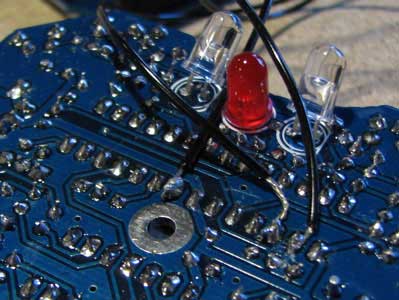
You need to solder a couple of extra wires onto the Asuro to program it. The wires soldered to the adjacent pins go to the RX and TX on the Arduino board (pins 0 and 1). The other wire goes to ground on the Arduino board.
Connect the wires to the right pins. Connect the USB cable to the Arduino board and the computer. You can upload programs straight from the Arduino environment. Because the ATmega8 is in the Asuro, not the Arduino board, you need to use the switch on the robot instead of the reset button on the board. Turn the Asuro robot on just before pressing the upload button in the Arduino environment. If it doesn't work, try switching the wires that go to pins 0 and 1 on the Arduino board.
Asuro Pins
Status led (red): digital pin 2
Front light led: digital pin 6
Status led (green): digital pin 8
Status led (yellow): digital pin 2+8
Left motor speed: digital pin 9 (pwm)
Right motor speed: digital pin 10 (pwm)
Infrared transmitter LED: digital pin 11
Bottom light detection transistors (LED-looking)
Left: analog input pin 3
Right: analog input pin 2
Left motor direction
Forward: pin 4 LOW, pin 5 HIGH
Reverse: pin 4 HIGH, pin 5 LOW
Right motor direction
Forward: pin 12 LOW, pin 13 HIGH
Reverse: pin 12 HIGH, pin 13 LOW
Front button detection
Checking the front buttons is made by sending voltage from digital out 3, and reading analogue in 4. Depending on which button(s) that are pressed, different resistors are connected on the asuro PCB and an unique analogue signal will return to analogue in 4, defining the buttons pressed.
Odometric speed control
Odometric infrared LED: digital pin 7
Left odometric infrared sensor: analog in 1
Right odometric infrared sensor: analog in 0
Arduino sketch for simple controls:
Attach:simplecontrols.zip
An Arduino library and a modified bootloader is also available,
based on these sketch.
Checkout the Asurino page for further information.
The normal serial commands (from the reference) should work.
This Asuro wiki (in German) has more information.