:: 4 Legs, 3 Servos, 2 Battery Packs, 1 Arduino :: This project is a custom chassis 4 leg walker from and Arduino, 3 Servos, and 2 Battery packs.
The concept behind this project was inspired by CrabFu's turtle robot. He does a nice job of showing the relationship between the phases of the legs and the torso movement. Figure 1 shows two examples one with standard servos (top) and one with pico servos (bottom). The batteries are oriented differently in the bottom diagram from that in Figure 1.
 Figure 1 Two different layouts for the components.
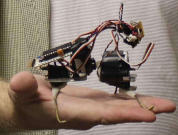 Figure 2 The robot in my hand for scale
 Figure 3 Detailed picture of the robot
The feet and certain connections and braces are made with ShapeLock for convenience.
The Physical Layout
The chassis is very simple. Two servos are oriented so the spindle is pointing down. The remaining servo connects the front half to the back half and provides the ability to twist the waist of the robot. Figure 4 shows a rough picture of the layout of the servos, batteries, and legs.  Figure 4 While the figure does show a +/-30 degree swing I suggest you play with this number for your chassis. It is a parameter that is interesting to "tune."
Block Diagram
No block diagram is really needed for this robot. The servos are wired to +Vcc, Gnd, and a digital pin. The servo class in the latest Arduino development tools is used. So basically power the Arduino and Servos from the batteries. Then wire the servo control lines to a digital pin on the Arduino and you are ready to go.
Torque Sensing
Optionally I have been experimenting with a current sensing circuit added to the ground leg of the servos. Figure 3 is the simple resistive circuit that is used. I have experimented with 2ohm resistors but I plan on switching 0.1ohm when they arrive. These three resistors are tied to analog lines so how much current the servo is drawing can be calculated by the voltage divided by .1 (or 2 ohm). But really I only care that the analog reading is proportional to the torque the servo is exerting.
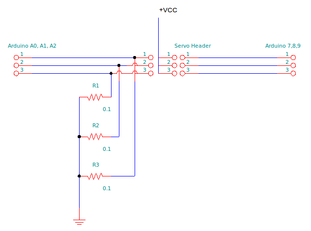 Figure 3
Software
The software is relatively simple for this chassis as well. Basically the front and back servos move exactly opposite of each other. So when the back-left foot is forward the front-left foot is backward. The waist simply moves 1/2 way through the time that the back and front servos are in position. Said another you move the front an back to an extreme position (opposite of each other) and then move the waist to the other extreme. Interestingly this simple Front/Back extreme then Waist extreme then other Front/Back extreme then other Waist extreme is all there is to forward (and played in reverse) backward motion. Turning left and right I thought might be trickier but it was simple also. You simply change one limit in the waist. So to turn right do not go to the extreme on the right twist in the waist only go to center. Left is simply going to center not to the extreme on the left twist in the waist. The front and back servos cycle the same in forward, backward, left or right motion.
- #include <Servo.h>
- Servo waist,front,back;
- #define wCenter 80
- #define fCenter 70
- #define bCenter 70
- #define wSwing 40
- #define fSwing 40
- #define bSwing 30
- #define FORWARD 0
- #define BACKWARD 1
- #define LEFT 2
- #define RIGHT 3
- #define STOP 4
- int wPos,fPos,bPos,cycle,dir;
- long start;
- void setup()
- {
- Serial.begin(9600);
- waist.attach(13);
- front.attach(12);
- back.attach(11);
- wPos=wCenter;
- fPos=fCenter;
- bPos=bCenter;
- dir=FORWARD;
- cycle=0;
- start=millis();
- Serial.println("iWaist,iFront,iBack");
- }
- void doBackward(int cycle) {
- if (cycle<12) wPos=wCenter+wSwing;
- else if (cycle<37) wPos=wCenter-wSwing;
- else if (cycle<62) wPos=wCenter+wSwing;
- else if (cycle<87) wPos=wCenter-wSwing;
- else wPos=wCenter+wSwing;
- if (cycle<25) fPos=fCenter+fSwing;
- else if (cycle<50) fPos=fCenter-fSwing;
- else if (cycle<75) fPos=fCenter+fSwing;
- else fPos=fCenter-fSwing;
- if (cycle<25) bPos=bCenter-bSwing;
- else if (cycle<50) bPos=bCenter+bSwing;
- else if (cycle<75) bPos=bCenter-bSwing;
- else bPos=bCenter+bSwing;
- }
- void doForward(int cycle) {
- doBackward(100-cycle);
- }
- void doLeft(int cycle) {
- doBackward(100-cycle);
- if (wPos>wCenter) wPos=wCenter;
- }
- void doRight(int cycle) {
- doBackward(100-cycle);
- if (wPos<wCenter) wPos=wCenter;
- }
- void doStop(){
- wPos=wCenter;
- fPos=fCenter;
- bPos=bCenter;
- }
- void posUpdate() {
- cycle=(cycle+1)%100; // 100 step cycle
- switch(dir) {
- case FORWARD: doForward(cycle); break;
- case BACKWARD: doBackward(cycle); break;
- case LEFT: doLeft(cycle); break;
- case RIGHT: doRight(cycle); break;
- case STOP: doStop(); break;
- }
- }
- void loop()
- {
- posUpdate();
- waist.write(wPos);
- front.write(fPos);
- back.write(bPos);
- long iWaist=analogRead(0);
- long iFront=analogRead(1);
- long iBack=analogRead(2);
- Serial.print(iWaist,10);
- Serial.print(",");
- Serial.print(iFront,10);
- Serial.print(",");
- Serial.print(iBack,10);
- Serial.println();
- delay(20);
- long t=millis()-start;
- if (t <10000) dir=FORWARD;
- else if (t < 20000) dir=BACKWARD;
- else if (t < 30000) dir=LEFT;
- else if (t < 40000) dir=RIGHT;
- else dir=STOP;
- }
Constants fCenter, bCenter, and wCenter are the center positions for each servo. So if you chassis is a bit off just change these to tweak alignment of the chassis. Constants fSwing, bSwing, and wSwing are the degrees to swing between.
This version will walk slow but stream torques to the serial port. This allows you to capture torques for data logging. Just comment out the Serial.??? calls in the loop body to remove this extra delay.
What is next
I hope to gather some interesting torque information to see if I can detect bumping into walls or drop-offs with torque being different than normal for those situations. This would mean the robot could "sense" walls and dropp-offs with no more circuitry than that discussed here.
Karl http://www.coloradomesa.edu/~kcastlet
Thanks Noah for the detailed pictures.
Update that includes head and sensors is at ThoughtfulWalker