DS1302RTC library
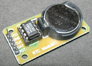
The DS1302 trickle-charge timekeeping chip contains a real-time clock/calendar and 31 bytes of static RAM. It communicates with a microprocessor via a simple serial interface. The real-time clock/calendar provides seconds, minutes, hours, day, date, month, and year information. The end of the month date is automatically adjusted for months with fewer than 31 days, including corrections for leap year. The clock operates in either the 24-hour or 12-hour format with an AM/PM indicator.
Library
Arduino library to support the Maxim Integrated DS1302 Real-Time Clocks. This library is intended for use with the Arduino Time.h library, http://www.arduino.cc/playground/Code/Time.
The DS1302RTC library is a drop-in replacement for the DS1307RTC.h library by Michael Margolis that is supplied with the Arduino Time library above. To change from using a DS1307 RTC to a DS1302 RTC, it is only necessary to change the #include statement to include DS1302RTC.h instead of DS1307RTC.h.
This library also implements functions to support the additional features of the DS1302:
Whether used with the DS1302, the user is responsible for ensuring reads
and writes do not exceed the device's address space
(0x80-0x90 for DS1302 clock data and 0xC0-0xFC RAM data);
no bounds checking is done by this library.
The DS1302 uses a 3-wire interface:
It is not I2C, not OneWire, and not SPI. So the standard libraries can not be used.
The "Chip Enable" pin was called "/Reset" before.
The chip has internal pull-down registers. This keeps the chip disabled, even if the pins of the Arduino are floating.
In burst mode, all the clock data is read at once. This is to prevent a rollover of a digit during reading. The read data is from an internal buffer.
The DS1302 has 31 of ram, which can be used to store data. The contents will be lost if the Arduino is off, and the backup battery gets empty. It is better to store data in the EEPROM of the Arduino.
The DS1302 has a build-in trickle charger. That can be used for example with a rechargeble battery or a supercap.
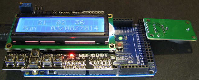
Connection and example
Install the module, so that all contacts occurred in digital inputs.
//
// A quick demo of how to use DS1302-library to make a quick
// clock using a DS1302 and a 16x2 LCD.
//
// I assume you know how to connect the DS1302 and LCD.
// DS1302: CE pin -> Arduino Digital 27
// I/O pin -> Arduino Digital 29
// SCLK pin -> Arduino Digital 31
// VCC pin -> Arduino Digital 33
// GND pin -> Arduino Digital 35
//
// LCD: DB7 -> Arduino Digital 7
// DB6 -> Arduino Digital 6
// DB5 -> Arduino Digital 5
// DB4 -> Arduino Digital 4
// E -> Arduino Digital 9
// RS -> Arduino Digital 8
#include <LiquidCrystal.h>
#include <DS1302RTC.h>
#include <Time.h>
// Init the DS1302
// Set pins: CE, IO,CLK
DS1302RTC RTC(27, 29, 31);
// Optional connection for RTC module
#define DS1302_GND_PIN 33
#define DS1302_VCC_PIN 35
// Init the LCD
// initialize the library with the numbers of the interface pins
// lcd(RS, E, d4, d5, d6, d7)
LiquidCrystal lcd(8, 9, 4, 5, 6, 7);
void setup()
{
// Setup LCD to 16x2 characters
lcd.begin(16, 2);
// Activate RTC module
digitalWrite(DS1302_GND_PIN, LOW);
pinMode(DS1302_GND_PIN, OUTPUT);
digitalWrite(DS1302_VCC_PIN, HIGH);
pinMode(DS1302_VCC_PIN, OUTPUT);
lcd.print("RTC activated");
delay(500);
// Check clock oscillation
lcd.clear();
if (RTC.haltRTC())
lcd.print("Clock stopped!");
else
lcd.print("Clock working.");
// Check write-protection
lcd.setCursor(0,1);
if (RTC.writeEN())
lcd.print("Write allowed.");
else
lcd.print("Write protected.");
delay ( 2000 );
// Setup Time library
lcd.clear();
lcd.print("RTC Sync");
setSyncProvider(RTC.get); // the function to get the time from the RTC
if(timeStatus() == timeSet)
lcd.print(" Ok!");
else
lcd.print(" FAIL!");
delay ( 2000 );
lcd.clear();
}
void loop()
{
// Display time centered on the upper line
lcd.setCursor(3, 0);
print2digits(hour());
lcd.print(" ");
print2digits(minute());
lcd.print(" ");
print2digits(second());
// Display abbreviated Day-of-Week in the lower left corner
lcd.setCursor(0, 1);
lcd.print(dayShortStr(weekday()));
// Display date in the lower right corner
lcd.setCursor(5, 1);
lcd.print(" ");
print2digits(day());
lcd.print("/");
print2digits(month());
lcd.print("/");
lcd.print(year());
// Warning!
if(timeStatus() != timeSet) {
lcd.setCursor(0, 1);
lcd.print(F("RTC ERROR: SYNC!"));
}
delay ( 1000 ); // Wait approx 1 sec
}
void print2digits(int number) {
// Output leading zero
if (number >= 0 && number < 10) {
lcd.write('0');
}
lcd.print(number);
}