I2C bi-directional level shifter
Introduction
This page is about a bi-directional level shifter for the I2C-bus: what it is, why you need it and when you can manage without.
A level shifter shifts the voltages of the bus signals so that devices of different voltages can communicate over the bus.
This purpose of this page is to collect together all the relevant information (for example from the forums), and you are invited to add your own solution.
Connecting 3.3V I2C components directly to the Arduino.
A 3.3V I2C component can be connected directly to the Arduino, by using the 3.3V of the Arduino board, and using two 4k7 pull-up resistors to the 3.3V, but you have to know the risks.
The Arduino boards use AVR microprocessors, most of which run at run at 5 Volts, and most of those Arduino Boards have a voltage regulator for 3.3 V which can be used for those components that need it.
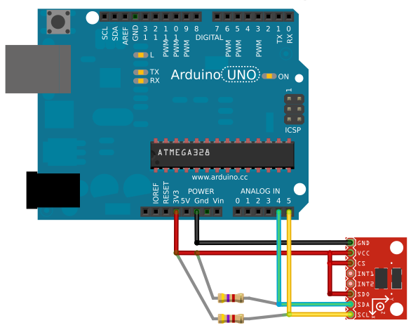
Multiple 3.3V I2C components can be added to this bus.
Many I2C devices operate over a range of voltages; it is possible that all your I2C components will work with 3.3V.
There has been some confusion about the minimum voltage for a 'high' level. For the normal digital input pins of the ATmega328p this is 0.6 * Vcc. However, for the I2C pins it is 0.7 * Vcc; in the datasheet this is called VIH (see Section 29.7 of the datasheet: 'Two-wire Serial Interface Characteristics'). Even the Arduino Leonardo and Arduino Micro (both of which use the ATmega32U4) require 0.7 * Vcc for 'high' level of the I2C bus, although their normal digital inputs are LVTTL and require only 1.9V. For 5V powered micros, the I2C high level should be at least 3.5V to meet specification; using the 3.3V I2C-bus for a 5V Arduino is living on the edge, hoping that the 3.3V will be recognized as a digital high. Since the I2C-bus is rather slow, the 4k7 pull-up resistors will pull the signal fast enough to 3.3V, and with the help of the internal pull-up resistors the Arduino will work with a 3.3V I2C-bus most of the time.
5V I2C components can be connected to the SDA and SCL lines of the 3.3V I2C-bus. A high level will be 3.3V and not 5V, but in most cases it's enough to make it work.
Internal pull-up resistors activated by Wire library.
The AVR microcontroller in the Arduino features a Two Wire Interface (TWI), which is I2C compatible. The SDA and SCL lines can be programmed to have internal pull-up resistors and the function Wire.begin() from the Wire library of Arduino 1.0 (in 2012) enables them; they are connected to Vcc which could violate the specifications of an I2C component if the microcontroller is running off 5V.
If two external pull-up resistors of 4k7 to 3.3V are used, the voltages on the SDA and SCL interconnections are only raised a little above 3.3V by the internal pull-up resistors, which are usually between 20k and 50k (exceptions: Due 50k to 150k, Mega2560 10k). However, the total currents flowing in the two internal pull-up resistors via the external pull-up resistors can easily exceed the current drawn by the 3.3V device. The 3.3V regulator of the Arduino will then not function and the 3.3V rail can go significantly higher than the maximum rating of the 3.3V device. This can be avoided by placing a resistor between 3.3V and Gnd to provide additional load for the 3.3V regulator. The maximum value of this resistor will depend on the particular Arduino's pull-up resistor specification and the minimum current drawn by the 3.3V device. For a Uno, a value of 22k should suffice even if the current drawn by the 3.3V device is only a few microamps.
This is a controversial subject with many opinions, but no one has yet reported a chip being damaged this way (but you do need those two 4k7 resistors).
Outside specs, (usually) works anyway
Connecting the 5V Arduino directly to a single 3.3V-powered I2C chip usually works, even though it violates official specifications in multiple ways. In practice, Arduino's internal pull-ups are so weak that ESD protection diodes inside the 3.3V chip limit the voltage (if any exceptions are discovered, where a chip is damaged or just doesn't work properly, please edit this page).
Of course, following the official I2C specification (stronger pull-up resistors) and avoiding higher voltage signals at any 3.3V chip is best. Any "serious" project should follow all technical specifications.
Arduino Mega 2560 has onboard pull-up resistors.
The Arduino Mega 2560 has 10k pull-up resistors on the SDA and SCL line to 5V. Therefore it is less compatible with a 3.3V I2C bus. A level shifter is recommended for the Arduino Mega 2560 to protect 3.3V sensors connected to the I2C bus.
Incompatible voltages
I2C components that use 1.8V or 2.8V cannot connect directly to the Arduino. In that case a level shifter must be used. Also for 3.3V I2C components a level shifter is sometimes used.
Bi-directional level shifter.
A level shifter can be used to do a voltage shift of the bi-directional signals of the I2C-bus (SDA and SCL).
This creates two groups on the I2C-bus, one group with the 5V and one group with a lower voltage. Once the level shifter is implemented, any combination of 3.3V and 5V components can be made and all within the I2C specifications.
Below is a list of possibilities:
Use two MOSFETs.
This is the approach most often used.
The Philips Applications Note AN97055 explains it.
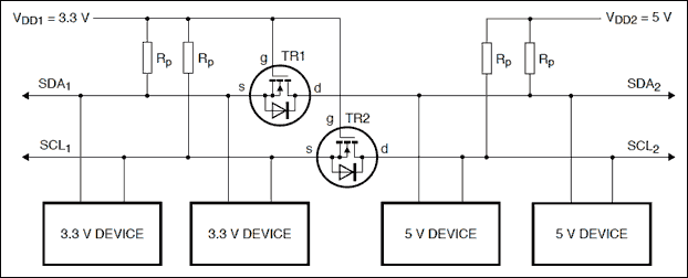
The MOSFETs must be types that activate with a very low gate voltage, for example BSS138 or TN2501.
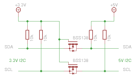
The resistors are not part of the level shifter; they are the pull-up resistors required by the I2C bus. In this case they have to be on both sides of the level shifter.
Each MOSFET conducts if the signal rail on either side is pulled low. If the source side is pulled low, the gate becomes positive with respect to the source; if the drain side is pulled low, the body diode conducts, bringing the source voltage down until the gate-source voltage is high enough to make the transistor conductive. The gate is always connected to the lower of the two supply voltages.
A device that pulls a line down has to handle the current through both resistors (on the 3.3V side and on the 5V side). That's why a higher value for the pull-up resistors is chosen, usually 10k.
Using a module.
Many common sensors are available as a module with an onboard level shifter. Some of these modules are specifically for the Arduino; others are intended for any microprocessor.
There are also modules which are just I2C level shifters.
Level shifter modules:
- The Sparkfun Logic Level Converter BOB-11978 : http://www.sparkfun.com/products/11978
It uses the BSS138 MOSFET, which can be used for bus voltages as low as 1.8V. - The Sparkfun PCA9306 Level Translator Breakout : http://www.sparkfun.com/products/10403
This uses the PC9306 chip. - The Adafruit 4-channel I2C-safe Bi-directional Logic Level Converter : http://www.adafruit.com/products/757
It also uses the BSS138.
Using a level shifter IC.
There are common IC's for level shifting:
- 74HC4050 (not bidirectional so not suitable for I2C ).
There are also special IC's for I2C level shifting:
- PCA9512
Using 4 transistors
A design idea at http://www.hagtech.com shows how to use 4 transistors. This is the document: http://www.hagtech.com/pdf/iic.pdf

The outer-most resistors are pull-up resistors for the I2C bus.
A device that pulls a line down will have to sink current through both resistors (on the 3.3V side, and on the 5V side) and also the current through the base of the transistor. Typical values for all resistors is 10k.
Using 2 transistors and 2 diodes
An alternative for the method with 4 transistors is using 2 diodes in stead of the 2 extra transistors, similar as in a MOSFET transistor. This would work equally to the MOSFET solution.
Interesting links
- Wikipedia about I2C: http://en.wikipedia.org/wiki/I%C2%B2C
- Extending the I2C over 5 meters: http://www.smacula.co.uk/2011/12/communicating-between-arduino-boards.html
- Level shifter at the TWI explanation: https://playground.arduino.cc/Code/ATMELTWI#shift
- A software I2C implementation, which can use any two pins of the Arduino is possible. Start with this article:
http://neuroelec.com/2011/02/soft-i2c-and-programmable-i2c-address/
This way even multiple I2C busses are possible.
- A i2c_scanner can be used to check if the device is connected to the i2c bus.