Matrix Keypad library
The Matrix Keypad how-to
This page last updated September 04, 2013, at 11:42 AM by gratefulfrog
This tutorial is based upon the
Matrix Keypad library
Navigation
- What is it?
- Identifying the keypad pins
- Notes on using the library
- Example
- Troubleshooting
- Modifying the library
What is it?
The Keypad library allows your Arduino to read a matrix type keypad. You can scavenge these keypads from old telephones or you can get them from almost any electronics parts store for less than $5 USD. They come in 3x4, 4x4 and various other configurations with words, letters and numbers written on the keys. This library is capable of supporting all of those.
Download latest
(This includes four example sketches.)

Identifying the keypad pins
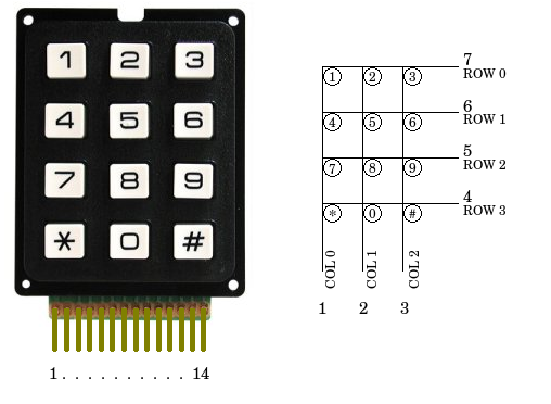
First you need to get a piece of paper and draw the right hand diagram as you see it below. I've already written my pin numbers (1,2,3 across the bottom and 7,6,5,4 down the right side) which you can just leave off of your drawing. Next, you are going to use your Ohm meter to find out which pins are connected to which keys. The first thing to do is count how many pins are on your keypad (as seen in the photo below.) The photo is showing 14 pins though not all of the pins are used. Don't worry, once you've completed this procedure you will know which pins are unused and can be ignored.
Procedure
- Connect your Ohm meter leads to pins 1 and 2.
- Press all the buttons until the meter indicates a closure.
- Write down the pin numbers next to the column and row for the key you just found. Example: Your meter is connected to pins 1 and 5. When you pressed the number 7 your meter reacted. Write 1 under COL0 and 5 next to ROW2.
- If the meter didn't react then move the meter lead from pin 2 to pin 3 and repeat steps 2 and 3 above.
- Now, keep moving the lead to the next pin and repeat steps 2 and 3 for each pin.
- Once you have reached the end move the first meter lead from pin 1 to pin 2 and repeat steps 2 and 3 while connecting the second meter lead to pins 3 through the highest pin.
- Once you have completely identified all the pins on the diagram then you can safely ignore any unused keypad pins. You are now ready to wire the keypad to your Arduino.
Notes on using the library
- The library is non-blocking which means you can press and hold the key all day long and your Arduino will continue processing the rest of your code.
- Consider, though, when you are writing your code that every delay() you use will take processing time away from the keypad. Something as short as delay(250) can make the keypad seem very unresponsive. And the same thing will happen if you sprinkle a bunch of delay(10)'s all through your code.
- The function getKey() returns a key value as soon as you press the key but it does not repeat automatically. Also, when you release the key you can track the key RELEASED event if you are using the eventListener feature of the library.
Example
< Find more examples on how to use the new library. >
/*  Keypadtest.pde
 *
 *  Demonstrate the simplest use of the  keypad library.
 *
 *  The first step is to connect your keypad to the
 *  Arduino  using the pin numbers listed below in
 *  rowPins[] and colPins[]. If you want to use different
 *  pins then  you  can  change  the  numbers below to
 *  match your setup.
 *
 */
#include <Keypad.h>

const byte ROWS = 4; // Four rows
const byte COLS = 3; // Three columns
// Define the Keymap
char keys[ROWS][COLS] = {
  {'1','2','3'},
  {'4','5','6'},
  {'7','8','9'},
  {'#','0','*'}
};
// Connect keypad ROW0, ROW1, ROW2 and ROW3 to these Arduino pins.
byte rowPins[ROWS] = { 9, 8, 7, 6 };
// Connect keypad COL0, COL1 and COL2 to these Arduino pins.
byte colPins[COLS] = { 12, 11, 10 };

// Create the Keypad
Keypad kpd = Keypad( makeKeymap(keys), rowPins, colPins, ROWS, COLS );

#define ledpin 13

void setup()
{
  pinMode(ledpin,OUTPUT);
  digitalWrite(ledpin, HIGH);
  Serial.begin(9600);
}

void loop()
{
  char key = kpd.getKey();
  if(key)  // Check for a valid key.
  {
    switch (key)
    {
      case '*':
        digitalWrite(ledpin, LOW);
        break;
      case '#':
        digitalWrite(ledpin, HIGH);
        break;
      default:
        Serial.println(key);
    }
  }
}
Troubleshooting
1. You can pretty much connect your keypad to any pins you would like. Be careful not to use the serial pins (0 and 1) if you are using them for communication.
2. If key presses seem to take a long time to show up then you are probably using long delay()'s in your code. The same thing can happen if you use too many small delay()s like delay(10).
3. Make sure you understand the pin mappings and have the keypad wired up to match. If you wired the pins incorrectly (and already soldered them in) then you may be able to fix it by redefining the pins and/or keymap to make your keypad work.
Modifying the library
The library supports user defined pins and keymaps so it should not be necessary to change the library. If you do then you need to make sure you save your files back to the proper folder under \$ArduinoHome$\libraries\. You may also have to exit and restart the Arduino IDE software for it to recognize any new files in your library's folder.