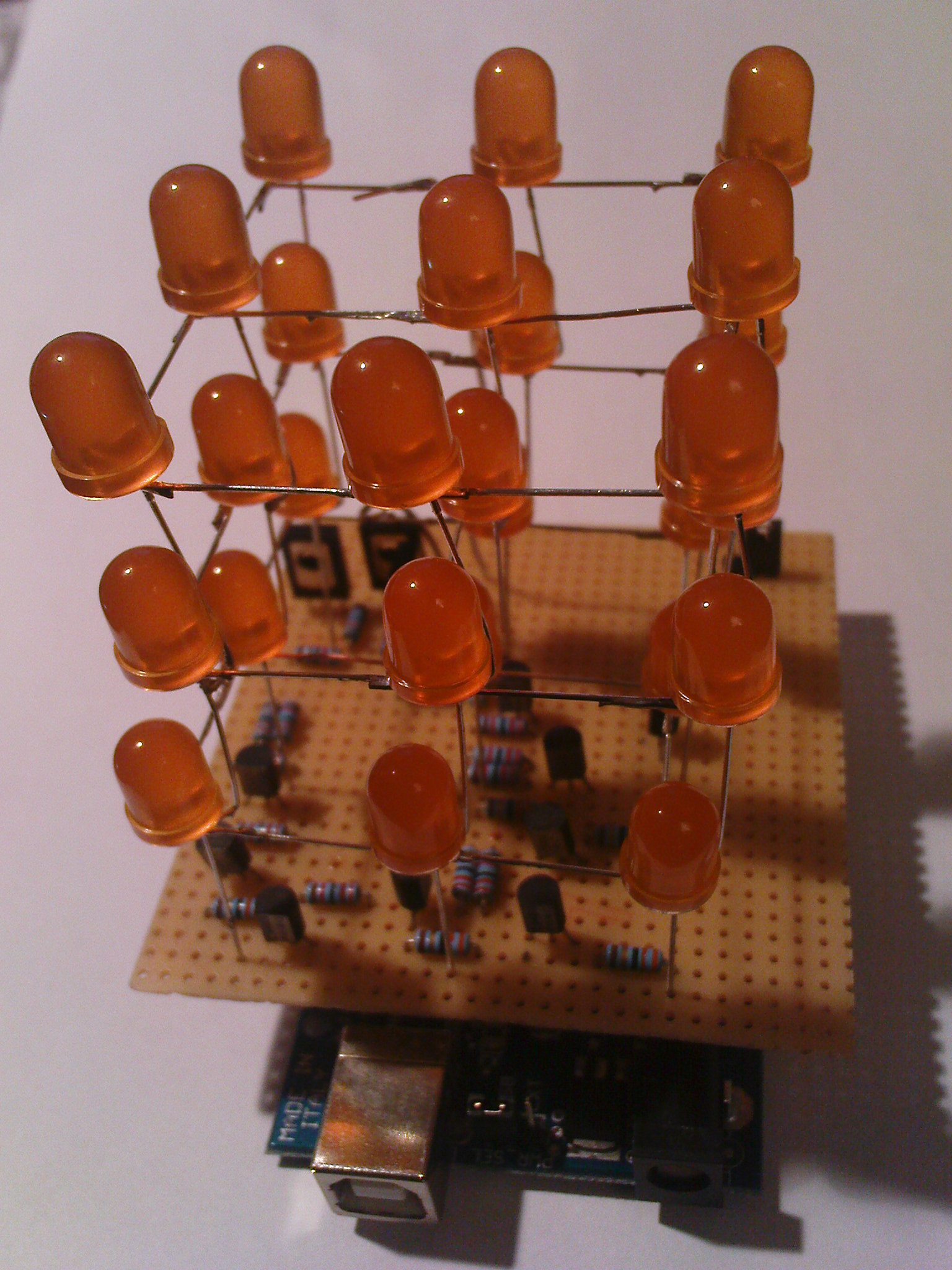
Multiplexed 3x3 LED Cube Arduino Diecimila Shield
(click image for full size)
Inspired by the MAKE magazines cubes (Workshop, Weekend Workshop).
The rows (LED anodes, AN1-3) are driven by BD140 PNP transistors switching +5V on HIGH, the colums (LED cathodes, CA1-9) are driven by BC548 NPN transistors, switchen GND on LOW.
The schematic includes an external power supply, which I chose not to use. Simply leave the 7805/caps/DC-jack out. The shield is USB powered, I re-programmed the FTDI controller to register 500 mA using their MProg tool (did not work from VirtualBox, though). If you choose to use external power:
- The Arduino Diecimila voltage regulator can't handle the power (at least not with the existing cooling), so you need your own one.
- The resistors are designed to deliver ~42 mA to the LEDs (I used orange 8mm Kingbright LEDs) to compensate for the multiplexing. This leaves some room for the Arduino etc to the 500mA limit (the Diecimila has a polyfuse that protects the USB-port).
A final note: yes, the headers on the solder-side are tricky to solder and you have to S-bend them ugly. I did not design the Diecimila board ... Using the protoshield as an adapter to normal grid-size (the space between the digital I/O connectors is just 0.05") only came to my mind when I noticed the problem, when the rest was already soldered.
If you have questions, mail me: angreifen <at> gmail.com
Thanks to Risto + Sebastian for a lot of advice.
