MMA7455 Accelerometer
The Freescale MMA7455L sensor is a 3-axis, 10-bit accelerometer with a digital interface.
This page provides information and a sketch to get the MMA7455 running with I2C, and to get to know the MMA7455.
Freescale has good information about this accelerometer, and Application Notes: http://www.freescale.com/webapp/sps/site/prod_summary.jsp?code=MMA745xL
For other programs and sensors, see the Accelerometer-section in the playground index: Accelerometer
Things to know
- The 10-bit values of the accelerometer are 10-bit signed integers. Some code is needed to convert them into normal signed integers of 16-bits.
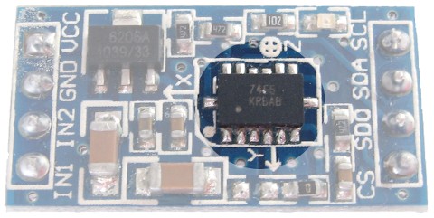
- Soldering this chip can be very hard. There are however many easy to use modules with this accelerometer. Some modules have a voltage regulator to make 3.3V for the accelerometer.
- The MMA7455 has internal offset registers. But the actual offset of the accelerometer changes if those offset registers are used.
- The chip is temperature compensated. There is even a temperature register, but reading that register returns always a zero.
- The MMA7455 is able to generate an interrupt for a certain level or pulse. But only one mode can be used at one time ("Measurement" or "Level Detection" or "Pulse Detection").
Conversion of 10-bits value
The MMA7455 has two sets registers for the x, y, and z values of the accelerometer. A set of 8-bit values for fast and easy use, and a set of 10-bit values for more accuracy.
The 10-bit value uses two registers for a LSB (least significant byte) and a MSB (most significant byte).
In my sketch on this page, I don't use the 8-bit value, but only the 10-bits value.
The LSB part is copied from the register of the MMA7455 and used as it is. The MSB part is converted for a 16-bit integer.
The output is 10-bits and could be negative. To use the output as a 16-bit signed integer, the sign bit (bit 9) of the msb is tested, and if it is set (indicating a negative value), it is extended for the 16 bits.
  if (x_msb & 0x02)    // Bit 9 is sign bit.
    x_msb |= 0xFC;     // Stretch bit 9 over other bits.
Collecting the 10-bits values (6 bytes) could be almost as fast as collecting the 8-bits values (3 bytes), by retrieving all 6 bytes in a single I2C-bus session. The MMA7455 is capable to receive or send multiple bytes.
Code
The code below is for Arduino 1.0.1 and I2C-bus communication. For the I2C-bus the /CS pin of the chip must be connected to the supply voltage (the DVDD_IO pin), or a pull-up resistor to DVDD_IO could be used.
A i2c_scanner can be used to check if the device is connected to the i2c bus.
The code uses the Arduino functions as much as possible. It can be used as a start and can be used for a class or a library.
The code shows how the 10-bits accelerometer values should be used to get normal 'g'-force values. It also shows how the internal offset of the acceleromter can be used.
The sketch is about 7kbyte, and will fit in a ATmega8.
// ---------------------
//
// By arduino.cc user "Krodal".
// May 2012
// Open Source / Public Domain
//
// Fixes to union and type conversions by Arduino.cc user "Afroviking"
// August 2014
//
// Using Arduino 1.0.1
// It will not work with an older version, since Wire.endTransmission()
// uses a parameter to hold or release the I2C bus.
//
// Documentation:
// - The Freescale MMA7455L datasheet
// - The AN3468 Application Note (programming).
// - The AN3728 Application Note (calibrating offset).
//
// The MMA7455 can be used by writing and reading a single byte,
// but it is also capable to read and write multiple bytes.
//
// The accuracy is 10-bits.
//
#include <Wire.h>
// Register names according to the datasheet.
// Register 0x1C is sometimes called 'PW', and sometimes 'PD'.
// The two reserved registers can not be used.
#define MMA7455_XOUTL 0x00 // Read only, Output Value X LSB
#define MMA7455_XOUTH 0x01 // Read only, Output Value X MSB
#define MMA7455_YOUTL 0x02 // Read only, Output Value Y LSB
#define MMA7455_YOUTH 0x03 // Read only, Output Value Y MSB
#define MMA7455_ZOUTL 0x04 // Read only, Output Value Z LSB
#define MMA7455_ZOUTH 0x05 // Read only, Output Value Z MSB
#define MMA7455_XOUT8 0x06 // Read only, Output Value X 8 bits
#define MMA7455_YOUT8 0x07 // Read only, Output Value Y 8 bits
#define MMA7455_ZOUT8 0x08 // Read only, Output Value Z 8 bits
#define MMA7455_STATUS 0x09 // Read only, Status Register
#define MMA7455_DETSRC 0x0A // Read only, Detection Source Register
#define MMA7455_TOUT 0x0B // Temperature Output Value (Optional)
#define MMA7455_RESERVED1 0x0C // Reserved
#define MMA7455_I2CAD 0x0D // Read/Write, I2C Device Address
#define MMA7455_USRINF 0x0E // Read only, User Information (Optional)
#define MMA7455_WHOAMI 0x0F // Read only, "Who am I" value (Optional)
#define MMA7455_XOFFL 0x10 // Read/Write, Offset Drift X LSB
#define MMA7455_XOFFH 0x11 // Read/Write, Offset Drift X MSB
#define MMA7455_YOFFL 0x12 // Read/Write, Offset Drift Y LSB
#define MMA7455_YOFFH 0x13 // Read/Write, Offset Drift Y MSB
#define MMA7455_ZOFFL 0x14 // Read/Write, Offset Drift Z LSB
#define MMA7455_ZOFFH 0x15 // Read/Write, Offset Drift Z MSB
#define MMA7455_MCTL 0x16 // Read/Write, Mode Control Register
#define MMA7455_INTRST 0x17 // Read/Write, Interrupt Latch Reset
#define MMA7455_CTL1 0x18 // Read/Write, Control 1 Register
#define MMA7455_CTL2 0x19 // Read/Write, Control 2 Register
#define MMA7455_LDTH 0x1A // Read/Write, Level Detection Threshold Limit Value
#define MMA7455_PDTH 0x1B // Read/Write, Pulse Detection Threshold Limit Value
#define MMA7455_PD 0x1C // Read/Write, Pulse Duration Value
#define MMA7455_LT 0x1D // Read/Write, Latency Time Value (between pulses)
#define MMA7455_TW 0x1E // Read/Write, Time Window for Second Pulse Value
#define MMA7455_RESERVED2 0x1F // Reserved
// Defines for the bits, to be able to change
// between bit number and binary definition.
// By using the bit number, programming the MMA7455
// is like programming an AVR microcontroller.
// But instead of using "(1<<X)", or "_BV(X)",
// the Arduino "bit(X)" is used.
#define MMA7455_D0 0
#define MMA7455_D1 1
#define MMA7455_D2 2
#define MMA7455_D3 3
#define MMA7455_D4 4
#define MMA7455_D5 5
#define MMA7455_D6 6
#define MMA7455_D7 7
// Status Register
#define MMA7455_DRDY MMA7455_D0
#define MMA7455_DOVR MMA7455_D1
#define MMA7455_PERR MMA7455_D2
// Mode Control Register
#define MMA7455_MODE0 MMA7455_D0
#define MMA7455_MODE1 MMA7455_D1
#define MMA7455_GLVL0 MMA7455_D2
#define MMA7455_GLVL1 MMA7455_D3
#define MMA7455_STON MMA7455_D4
#define MMA7455_SPI3W MMA7455_D5
#define MMA7455_DRPD MMA7455_D6
// Control 1 Register
#define MMA7455_INTPIN MMA7455_D0
#define MMA7455_INTREG0 MMA7455_D1
#define MMA7455_INTREG1 MMA7455_D2
#define MMA7455_XDA MMA7455_D3
#define MMA7455_YDA MMA7455_D4
#define MMA7455_ZDA MMA7455_D5
#define MMA7455_THOPT MMA7455_D6
#define MMA7455_DFBW MMA7455_D7
// Control 2 Register
#define MMA7455_LDPL MMA7455_D0
#define MMA7455_PDPL MMA7455_D1
#define MMA7455_DRVO MMA7455_D2
// Interrupt Latch Reset Register
#define MMA7455_CLR_INT1 MMA7455_D0
#define MMA7455_CLR_INT2 MMA7455_D1
// Detection Source Register
#define MMA7455_INT1 MMA7455_D0
#define MMA7455_INT2 MMA7455_D1
#define MMA7455_PDZ MMA7455_D2
#define MMA7455_PDY MMA7455_D3
#define MMA7455_PDX MMA7455_D4
#define MMA7455_LDZ MMA7455_D5
#define MMA7455_LDY MMA7455_D6
#define MMA7455_LDX MMA7455_D7
// I2C Device Address Register
#define MMA7455_I2CDIS MMA7455_D7
// Default I2C address for the MMA7455
#define MMA7455_I2C_ADDRESS 0x1D
// When using an union for the registers and
// the axis values, the byte order of the accelerometer
// should match the byte order of the compiler and AVR chip.
// Both have the lower byte at the lower address,
// so they match.
// This union is only used by the low level functions.
typedef union xyz_union
{
struct
{
uint8_t x_lsb;
uint8_t x_msb;
uint8_t y_lsb;
uint8_t y_msb;
uint8_t z_lsb;
uint8_t z_msb;
} reg;
struct
{
uint16_t x;
uint16_t y;
uint16_t z;
} value;
};
int led = 13;
void setup()
{
int error;
uint8_t c;
Serial.begin(9600);
Serial.println("Freescale MMA7455 accelerometer");
Serial.println("May 2012");
// Initialize the 'Wire' class for I2C-bus communication.
Wire.begin();
// Initialize the MMA7455, and set the offset.
error = MMA7455_init();
if (error == 0)
Serial.println("The MMA7455 is okay");
else
Serial.println("Check your wiring !");
// Read the Status Register
MMA7455_read(MMA7455_STATUS, &c, 1);
Serial.print("STATUS : ");
Serial.println(c,HEX);
// Read the "Who am I" value
MMA7455_read(MMA7455_WHOAMI, &c, 1);
Serial.print("WHOAMI : ");
Serial.println(c,HEX);
// Read the optional temperature output value (I always read zero)
MMA7455_read(MMA7455_TOUT, &c, 1);
Serial.print("TOUT : ");
Serial.println(c,DEC);
pinMode(led, OUTPUT);
}
void loop()
{
uint16_t x,y,z, error;
double dX,dY,dZ;
// The function MMA7455_xyz returns the 'g'-force
// as an integer in 64 per 'g'.
// set x,y,z to zero (they are not written in case of an error).
x = y = z = 0;
error = MMA7455_xyz(&x, &y, &z); // get the accelerometer values.
dX = (int16_t) x / 64.0; // calculate the 'g' values.
dY = (int16_t) y / 64.0;
dZ = (int16_t) z / 64.0;
Serial.print("error = ");
Serial.print(error, DEC);
Serial.print(", xyz g-forces = ");
Serial.print(dX, 3);
Serial.print(", ");
Serial.print(dY, 3);
Serial.print(", ");
Serial.print(dZ, 3);
Serial.println("");
if (dZ < 0.8)
{
digitalWrite(led, HIGH); // turn the LED on (HIGH is the voltage level)
}
else
{
digitalWrite(led, LOW); // turn the LED off by making the voltage LOW
}
delay(100);
}
// --------------------------------------------------------
// MMA7455_init
//
// Initialize the MMA7455.
// Set also the offset, assuming that the accelerometer is
// in flat horizontal position.
//
// Important notes about the offset:
// The sensor has internal registers to set an offset.
// But the offset could also be calculated by software.
// This function uses the internal offset registers
// of the sensor.
// That turned out to be bad idea, since setting the
// offset alters the actual offset of the sensor.
// A second offset calculation had to be implemented
// to fine tune the offset.
// Using software variables for the offset would be
// much better.
//
// The offset is influenced by the slightest vibration
// (like a computer on the table).
//
int MMA7455_init(void)
{
uint16_t x, y, z;
int error;
xyz_union xyz;
uint8_t c1, c2;
// Initialize the sensor
//
// Sensitivity:
// 2g : GLVL0
// 4g : GLVL1
// 8g : GLVL1 | GLVL0
// Mode:
// Standby : 0
// Measurement : MODE0
// Level Detection : MODE1
// Pulse Detection : MODE1 | MODE0
// There was no need to add functions to write and read
// a single byte. So only the two functions to write
// and read multiple bytes are used.
// Set mode for "2g sensitivity" and "Measurement Mode".
c1 = bit(MMA7455_GLVL0) | bit(MMA7455_MODE0);
error = MMA7455_write(MMA7455_MCTL, &c1, 1);
if (error != 0)
return (error);
// Read it back, to test the sensor and communication.
error = MMA7455_read(MMA7455_MCTL, &c2, 1);
if (error != 0)
return (error);
if (c1 != c2)
return (-99);
// Clear the offset registers.
// If the Arduino was reset or with a warm-boot,
// there still could be offset written in the sensor.
// Only with power-up the offset values of the sensor
// are zero.
xyz.value.x = xyz.value.y = xyz.value.z = 0;
error = MMA7455_write(MMA7455_XOFFL, (uint8_t *) &xyz, 6);
if (error != 0)
return (error);
// The mode has just been set, and the sensor is activated.
// To get a valid reading, wait some time.
delay(100);
#define USE_INTERNAL_OFFSET_REGISTERS
#ifdef USE_INTERNAL_OFFSET_REGISTERS
// Calcuate the offset.
//
// The values are 16-bits signed integers, but the sensor
// uses offsets of 11-bits signed integers.
// However that is not a problem,
// as long as the value is within the range.
// Assuming that the sensor is flat horizontal,
// the 'z'-axis should be 1 'g'. And 1 'g' is
// a value of 64 (if the 2g most sensitive setting
// is used).
// Note that the actual written value should be doubled
// for this sensor.
error = MMA7455_xyz (&x, &y, &z); // get the x,y,z values
if (error != 0)
return (error);
xyz.value.x = 2 * -x; // The sensor wants double values.
xyz.value.y = 2 * -y;
xyz.value.z = 2 * -(z-64); // 64 is for 1 'g' for z-axis.
error = MMA7455_write(MMA7455_XOFFL, (uint8_t *) &xyz, 6);
if (error != 0)
return (error);
// The offset has been set, and everything should be okay.
// But by setting the offset, the offset of the sensor
// changes.
// A second offset calculation has to be done after
// a short delay, to compensate for that.
delay(200);
error = MMA7455_xyz (&x, &y, &z); // get te x,y,z values again
if (error != 0)
return (error);
xyz.value.x += 2 * -x; // add to previous value
xyz.value.y += 2 * -y;
xyz.value.z += 2 * -(z-64); // 64 is for 1 'g' for z-axis.
// Write the offset for a second time.
// This time the offset is fine tuned.
error = MMA7455_write(MMA7455_XOFFL, (uint8_t *) &xyz, 6);
if (error != 0)
return (error);
#endif
return (0); // return : no error
}
// --------------------------------------------------------
// MMA7455_xyz
//
// Get the 'g' forces.
// The values are with integers as 64 per 'g'.
//
int MMA7455_xyz( uint16_t *pX, uint16_t *pY, uint16_t *pZ)
{
xyz_union xyz;
int error;
uint8_t c;
// Wait for status bit DRDY to indicate that
// all 3 axis are valid.
do
{
error = MMA7455_read (MMA7455_STATUS, &c, 1);
} while ( !bitRead(c, MMA7455_DRDY) && error == 0);
if (error != 0)
return (error);
// Read 6 bytes, containing the X,Y,Z information
// as 10-bit signed integers.
error = MMA7455_read (MMA7455_XOUTL, (uint8_t *) &xyz, 6);
if (error != 0)
return (error);
// The output is 10-bits and could be negative.
// To use the output as a 16-bit signed integer,
// the sign bit (bit 9) is extended for the 16 bits.
if (xyz.reg.x_msb & 0x02) // Bit 9 is sign bit.
xyz.reg.x_msb |= 0xFC; // Stretch bit 9 over other bits.
else
xyz.reg.x_msb &= 0x3;
if (xyz.reg.y_msb & 0x02)
xyz.reg.y_msb |= 0xFC;
else
xyz.reg.y_msb &= 0x3;
if (xyz.reg.z_msb & 0x02)
xyz.reg.z_msb |= 0xFC;
else
xyz.reg.z_msb &= 0x3;
// The result is the g-force in units of 64 per 'g'.
*pX = xyz.value.x;
*pY = xyz.value.y;
*pZ = xyz.value.z;
return (0); // return : no error
}
// --------------------------------------------------------
// MMA7455_read
//
// This is a common function to read multiple bytes
// from an I2C device.
//
// It uses the boolean parameter for Wire.endTransMission()
// to be able to hold or release the I2C-bus.
// This is implemented in Arduino 1.0.1.
//
// Only this function is used to read.
// There is no function for a single byte.
//
int MMA7455_read(int start, uint8_t *buffer, int size)
{
int i, n, error;
Wire.beginTransmission(MMA7455_I2C_ADDRESS);
n = Wire.write(start);
if (n != 1)
return (-10);
n = Wire.endTransmission(false); // hold the I2C-bus
if (n != 0)
return (n);
// Third parameter is true: relase I2C-bus after data is read.
Wire.requestFrom(MMA7455_I2C_ADDRESS, size, true);
i = 0;
while(Wire.available() && i<size)
{
buffer[i++]=Wire.read();
}
if ( i != size)
return (-11);
return (0); // return : no error
}
// --------------------------------------------------------
// MMA7455_write
//
// This is a common function to write multiple bytes
// to an I2C device.
//
// Only this function is used to write.
// There is no function for a single byte.
//
int MMA7455_write(int start, const uint8_t *pData, int size)
{
int n, error;
Wire.beginTransmission(MMA7455_I2C_ADDRESS);
n = Wire.write(start); // write the start address
if (n != 1)
return (-20);
n = Wire.write(pData, size); // write data bytes
if (n != size)
return (-21);
error = Wire.endTransmission(true); // release the I2C-bus
if (error != 0)
return (error);
return (0); // return : no error
}