Multiplexing the MAX72xx to Drive a 2 Color Matrix
Overview:
This article describes a technique where 2 MAX72xx can be used in combination to drive a 2 color common cathode matrix. The technique involves tying the row (digit) lines together on the chips, and alternating the shutdown of each chip in code. The method is described in a Maxim application note http://www.maxim-ic.com/appnotes.cfm/appnote_number/1004
It is possible that this technique can be expanded to work with 3 MAX to drive an RGB matrix, however, as I have not done this myself, I can't vouch for it. Personally, I believe that if your after RGB you are better off using another technique - such as the 595 shift register - as they are proven to work.
Marc MERLIN has written a bi color/RGB PWM driver for bi/tricolor matrices using only direct IO and/or shift registers, you can see his page here:
- http://marc.merlins.org/perso/arduino/post_2015-01-06_Driver-for-direct-driving-single-to-3-color-LED-Matrices-with-software-PWM.html
- https://github.com/marcmerlin/LED-Matrix/
- https://www.youtube.com/watch?v=tKCOY1tTtM4
This method will work better than using a MAX7219/MAX7221 for multiple colors and PWM but will be more taxing on the arduino of course.
Note that the MAX7221 is definitely preferred over the MAX7219 for this technique. This is because in shutdown, the MAX7221 digit drivers are high impedance, rather than V+ as in the MAX7219.
However, I have used both parts in my projects with no noticeable difference. I don't know why the MAX7219 works - but it does! So if you only have MAX7219's it's worth trying them.
Inside The Matrix:
The following diagram shows how a common cathode RG matrix is wired. Note that the cathodes in each row are common for both colors. Since each MAX will be dedicated to driving one color, this means that the digit lines (rows) on the chips will also be connected together.

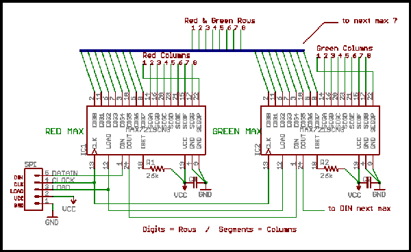
The Schematic:
Here we see the digit lines on the chips connected together. The segments (columns) from each chip go to the respective color.
Note that the segment for the decimal point is considered as column #1 in this scheme. This allows the matrix to be mapped according to the datasheet above - with Row 1 / Col 1 in the upper left corner.
The rest of the schematic is how multiple MAX's are normally chained together.
The Code:
The code below is a simple example that points out how the technique works in the sketch. It relies on LedControl the library that interfaces between the sketch and the MAX. The example also uses a timer that triggers the ISR.
The ISR - ISR(TIMER2_COMPA_vect)
The ISR's job is simply to put one or the other MAX in the shutdown mode and wake the other. This is critical, because there can not be more than one MAX driving the matrix at the same time.
A technique was tried where both MAXs were put in shutdown before pulling one out, but it seems you get better results by simply switching them.
Note that even while the MAX is in shutdown, it is still accepting commands.
The Timer
I've tried various timers for triggering the ISR - FrequencyTimer2, MsTimer2, etc. They all worked, but the simple CTC mode timer in this example has given the best results.
It is important to this technique that the ISR can be quickly disabled. As you will see, we do not want to be toggling shutdown when LedControl is sending commands to the chip.
In the example, the timer is set for about 650Hz. This means that each MAX is on 325 times / sec. This is about as fast as you can go. In fact, depending on what else is going on, you may need to slow it down. If the ISR is too fast, the display will be sluggish. If it's way too fast, the sketch will hang on delay()s.
Note there are also functions to enable and disable the ISR.
The Wrappers
The LedControl library is used to control the LEDs in the matrix. However, commands will get lost if the MAXs are toggling in and out of shutdown when LedControl is sending commands to the chip. Therefore "wrappers" are put around each of the functions that LedControl uses to control the LEDs. The wrappers simply turn off the ISR before the call, and turn it back on after the call.
Controlling the Matrix
With the above in place, the wrappers are called just like the you would call the LedControl. The address of each MAX is it's color.
Example
- /* RG Matrix Example v.2 8/1/08 BroHogan
- * Demos 2 color 8x8 matrix driven by 2 MAX7821's
- */
- #include "WProgram.h" // needed to compile with Rel. 0013 WHY?!
- #include "LedControl.h" // to drive the matrix
- #define ISR_FREQ 190 //190=650Hz // Sets the speed of the ISR - LOWER IS FASTER
- // prescaler is /128 - 125,000/ISR_FREQ+1 (i.e 249=500Hz, 190=650Hz)
- // Tweaked depending on the overhead in the ISR & and other factors in the sketch
- // Display will be slow if too FAST. Sketch will hang on delay() if way too fast!
- #define GREEN 0 // The address of the MAX7221 for the green leds
- #define RED 1 // The address of the MAX7221 for the red leds
- int maxInShutdown=GREEN; // tells which MAX7221 is currently off
- unsigned long ISRTime; // DEBUG to test how long in ISR
- LedControl lc=LedControl(10,9,8,2); // pins 10=DataIn, 9=CLK, 8=LOAD + 2 MAX7221s
- void setup() {
- lc.setIntensity(GREEN,15); // 0 = dim, 15 = full brightness
- lc.setIntensity(RED,12); // red needs less brightness
- setISRtimer(); // setup the timer
- startISR(); // start the timer to toggle shutdown
- }
- void loop() {
- // Simple demo, but gives 2 colors a pretty good workout
- SkipRows();
- delay(1000);
- ClearMatrix();
- delay(500);
- }
- /////////////////////////////ISR Timer Functions ///////////////////////////
- ISR(TIMER2_COMPA_vect) { //This ISR toggles shutdown between the 2MAX7221's
- if(maxInShutdown==RED){
- lc.shutdown(GREEN,true); // The order here is critical - Shutdown first!
- lc.shutdown(RED,false); // . . . Then restart the other.
- maxInShutdown=GREEN;
- }
- else {
- lc.shutdown(RED,true);
- lc.shutdown(GREEN,false);
- maxInShutdown=RED;
- }
- }
- void setISRtimer(){ // setup ISR timer controling toggleing
- TCCR2A = 0x02; // WGM22=0 + WGM21=1 + WGM20=0 = Mode2 (CTC)
- TCCR2B = 0x05; // CS22=1 + CS21=0 + CS20=1 = /128 prescaler (125kHz)
- TCNT2 = 0; // clear counter
- OCR2A = ISR_FREQ; // set TOP (divisor) - see #define
- }
- void startISR(){ // Starts the ISR
- TCNT2 = 0; // clear counter (needed here also)
- TIMSK2|=(1<<OCIE2A); // set interrupts=enabled (calls ISR(TIMER2_COMPA_vect)
- }
- void stopISR(){ // Stops the ISR
- TIMSK2&=~(1<<OCIE2A); // disable interrupts
- }
- //////////////////////// simple LED display routine /////////////////////////////
- void SkipRows() { // 1st pass alternates green & red, 2nd adds green to red making orange
- byte greenOn = true; // flag for lighting green for orange
- for(int row=0;row<8;row++) {
- for(int col=0;col<8;col++) {
- if (greenOn == true) SetLed(GREEN,row,col,true);
- else SetLed(RED,row,col,true);
- greenOn = !greenOn;
- }
- }
- delay(500); // only so you can see the first pass
- greenOn = !greenOn;
- for(int row=0;row<8;row++) {
- for(int col=0;col<8;col++) {
- delay(4); // only so you can see the update
- if (greenOn == true) SetLed(GREEN,row,col,true);
- greenOn = !greenOn;
- }
- }
- }
- ///////// Wrappers for LedControl functions . . . //////////
- void SetLed(byte Color, byte Row,byte Col, byte State){
- stopISR(); // disable interrupts - stop toggling shutdown when updating
- lc.setLed(Color,Row,Col,State);
- startISR(); // enable interrupts again
- }
- void SetRow(byte Color, byte Row, byte State){
- stopISR(); // disable interrupts - stop toggling shutdown when updating
- lc.setRow(Color,Row,State);
- startISR(); // enable interrupts again
- }
- void SetColumn(byte Color, byte Col, byte State){
- stopISR(); // disable interrupts - stop toggling shutdown when updating
- lc.setColumn(Color,Col,State);
- startISR(); // enable interrupts again
- }
- void ClearMatrix(){
- stopISR(); // disable interrupts - stop toggling shutdown when updating
- lc.clearDisplay(GREEN);
- lc.clearDisplay(RED);
- startISR(); // enable interrupts again
- }
Limitations:
- No PWM - There is no provision here allow you to dim the LED using PWM. Therefore an RGB matrix will only display 7 or so colors.
- Requires an ISR - You must live with an ISR that is almost always running in your code. (You can turn it off if a part of the application only needs 1 color.)
- Dimmer - Because the duty cycle is effectively cut in half, the matrix is about 20% dimmer then it would be without the multiplexing the chips. The good news is that matrix consumes less power. With all of the red and green Leds on (128 Leds), the 2 MAX chips and the matrix consume about 92mA in my tests. (This is average and not peak.)
- I have heard (from 2 sources now) that during attempts to drive 3 MAX72xx, the SetRow and SetColumn functions quit working. (Don't understand why!) However, simulating the SetRow functionality in the sketch works. Again, for 3 colors I'd suggest another technique.
Tips:
- Because the ISR is running you will find that things like generating a tone with a piezo, or reading an IR detector will not work, or not work well. The solution is to stop the ISR before using these devices - stopISR(), and restart the ISR when done - startISR().
- If more than two MAX72xx chips are being used, it is best to reverse the logic in the ISR. In otherwords, instead of "maxInShutdown" use something like "maxActive". You can still use the else ifs or even a switch statement.
- When adjusting the frequency of the ISR Timer, do it in small steps! (i.e. 5-10)
- [added 2/22/11] I've heard of someone using an external source (i.e. 555) to trigger the ISR. This may eliminate some of the caveats mentioned above - but I have no first hand knowledge of this.
License:
The source code here is released under the Terms of the GNU Lesser General Public License version 3.0.
That's all I know. BroHogan