R4571 Real Time Clock (ETM21E-02)
The R4571 is a Real Time Clock (RTC) with internal oscillator and alarm/interrupt functions. This chip can be found in some Epson printers with clock features.
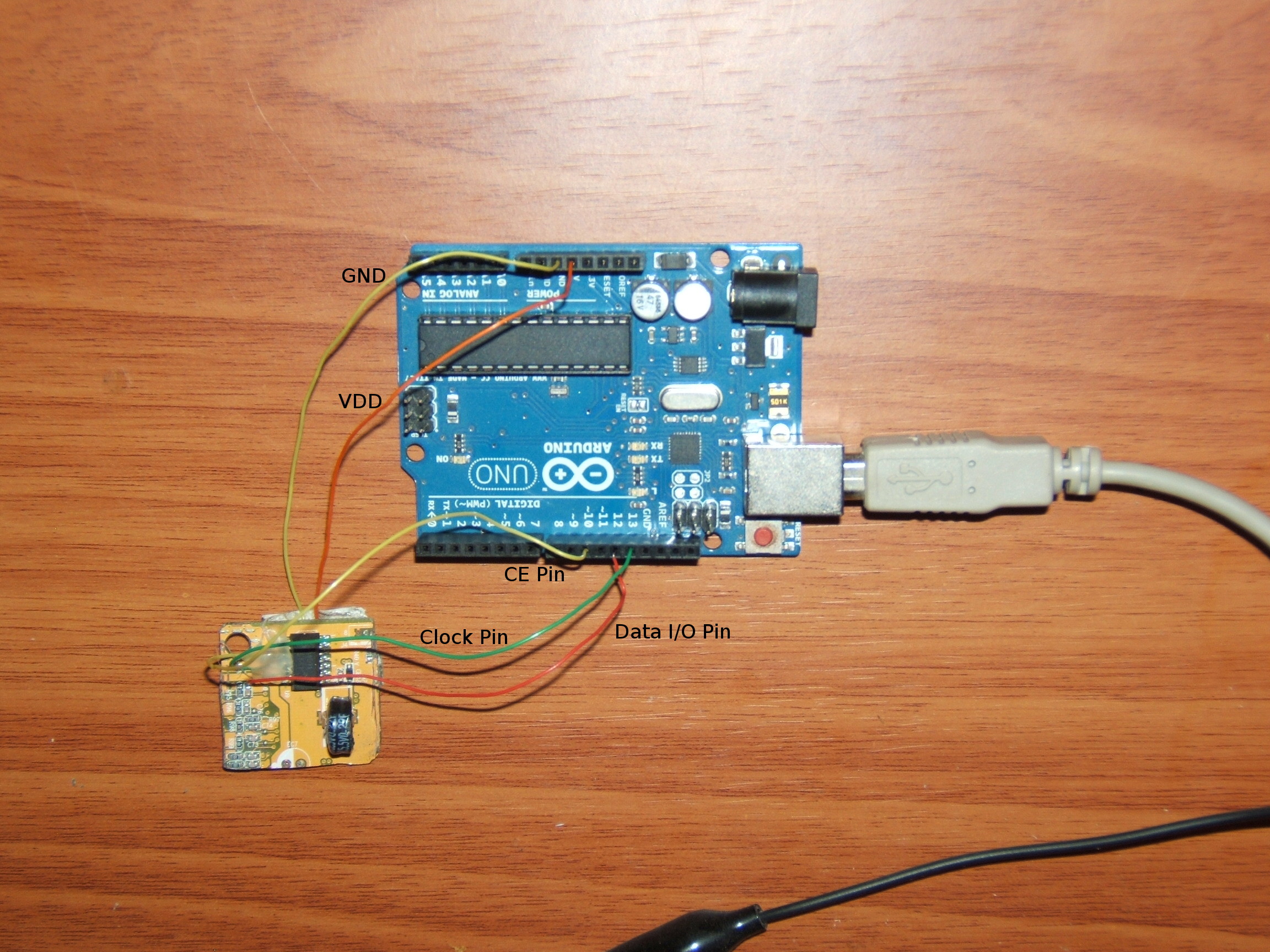
(photo by Blunoise, Public Domain)
Datasheet:
http://www.epsondevice.com/docs/qd/en/DownloadServlet?id=ID000392
Connect it to the Arduino:
The R4571 is connected to the Arduino using pins (CE, DIO, CLK) and Vdd can be connect to +5V (or +3.3V). FOUT chip pin can be used as a source clock (see notes) IRQ pin can be used as counter time interrupt.
The Vdd range is 1.6V - 5.5V and the battery it could be a lithium battery (see datasheet). Be careful to connect value minor than 3V because the DIO Pin High and Low voltage levels are based on Vdd (comunication problems)
Comunication protocol:
The R4571 use a 3-wire serial interface (Most Significant Bit First). How described in code section, to realize the protocol the arduino shiftIn and shiftOut functions have been used. To perform a write register operation call writeReg(register,value). To perform a read register operation call readReg(register).
The chip read/write one-shot access is based on fews steps:
- Set the Clock Pin to low:
   How it's described at CLK pin description in datasheet
   the read mode clockis on fall edge and the write mode
   clock is on raise edge.
   So, based on the shiftOut documentation
   (http://arduino.cc/en/Reference/ShiftOut) the clock pin
   must be setted LOW at beginning of any transmission
   because the comunication always start with a byte sended
   by arduino that contain operation mode and address.(see nexts points)
- Set CE Pin High
- Send the first byte:
   The first byte must contain read/write mode on first part and the register address on rest part.
   For a read operation byte first part must be 1001 (09h).
   For a write operation byte first part must be 0001 (01h).
   Example:to make a read operation on register 0x03 the first byte to transmit is 1001 0011 (0x93)
- Send/Receive the data (1 byte):
- On read operation the data is retrieved by calling the shiftIn function.
- On write operation data is sended to the device by calling shiftOut function.
- Set CE Pin Low : end of transmission
Time/Date read and set:
To read or set time and date just call the appropriate function:
- setTime(uint8_t hours , uint8_t minutes , uint8_t seconds);
- setDate (uint8_t weekDay,uint8_t day,uint8_t month,uint8_t year);
- getDate();
The week days starts from Sunday (value 0x01) to Saturday (value 0x07).
- Examples:
- set date “Fri 12 July 2013”: setDate(0x06,0x12,0x07,0x13)
- set time “12:00:00”: setTime(0x12,0x00,0x00)
- get date string: char * dateString = getDate()
this function return date in form “Fri 2013-07-12”
- Read a single address:
e.g.: get minutes value
- uint8_t minutes = readReg(0x01) ;
- //or
- uint8_t minutes = readReg(R4571_MIN);
Code:
- RTC_R4571.h
- //SET PIN HERE
- #define CE_PIN 10
- #define CLOCK_PIN 13
- #define DATA_PIN 12
- //RTC RX-4571 REGISTER
- #define R4571_SEC 0x00
- #define R4571_MIN 0x01
- #define R4571_HOURS 0x02
- #define R4571_WDAY 0x03
- #define R4571_DAY 0x04
- #define R4571_MONTH 0x05
- #define R4571_YEAR 0x06
- #define R4571_RAM 0x07
- #define R4571_MIN_ALARM 0x08
- #define R4571_HOURS_ALARM 0x09
- #define R4571_WDAY_ALARM 0x0A
- #define R4571_DAY_ALARM 0x0B
- #define R4571_TIMER_SETUP 0x0C
- #define R4571_TIMER_COUNTER 0x0D
- #define R4571_EXT_REGISTER 0x0E
- #define R4571_FLAG_REGISTER 0x0F
- #include <inttypes.h>
- #include <Arduino.h>
- class rtc_R4571
- {
- public:
- uint8_t readReg(unsigned char reg);
- void writeReg(uint8_t reg, uint8_t value);
- void setTime(uint8_t hours,uint8_t minutes,uint8_t seconds);
- void setDate(uint8_t weekDay,uint8_t day,uint8_t month,uint8_t year);
- char * getDate();
- rtc_R4571(); //class constructor: set pin directions
- };
- RTC_R4571.cpp
- #include "RTC_R4571.h"
- uint8_t rtc_R4571::readReg(unsigned char reg)
- {
- if (reg > 0x0F)
- return 0;
- pinMode(DATA_PIN, OUTPUT);
- digitalWrite(CLOCK_PIN, LOW); // set to rising edge (see https://arduino.cc/en/Reference/ShiftOut)
- digitalWrite(CE_PIN, 1);
- uint8_t completeAddr=0;
- completeAddr+=0x90; //read mode
- completeAddr+=reg;
- shiftOut(DATA_PIN,CLOCK_PIN,MSBFIRST,completeAddr); //set read mode on addr (send first 8 bit [mode|addr])
- pinMode(DATA_PIN, INPUT); //see datasheet
- uint8_t readVal=0;
- readVal = shiftIn(DATA_PIN, CLOCK_PIN, MSBFIRST); //read the data
- digitalWrite(CE_PIN, 0);
- return readVal;
- }
- void rtc_R4571::writeReg(uint8_t reg, uint8_t value)
- {
- pinMode(DATA_PIN, OUTPUT);
- digitalWrite(CLOCK_PIN, LOW);
- digitalWrite(CE_PIN, 1);
- uint8_t completeAddr=0;
- completeAddr+=0x10; //write mode
- completeAddr+=reg;
- shiftOut(DATA_PIN,CLOCK_PIN,MSBFIRST,completeAddr); //set write mode on addr
- shiftOut(DATA_PIN,CLOCK_PIN,MSBFIRST,value); //write data
- digitalWrite(CE_PIN, 0);
- }
- void rtc_R4571::setTime(uint8_t hours, uint8_t minutes, uint8_t seconds)
- {
- //example 12:05:00 -> setTime(0x12,0x05,0x00);
- writeReg(R4571_HOURS,hours);
- writeReg(R4571_MIN,minutes);
- writeReg(R4571_SEC,seconds);
- }
- void rtc_R4571::setDate(uint8_t weekDay, uint8_t day, uint8_t month, uint8_t year)
- {
- //Sun=0x01 ....... Sat=0x07
- //example Fri 12 July 2013 -> setDate(0x05,0x12,0x07,0x13);
- //if you want to set wday directly using writeReg
- //this value must be inserted (see datasheet):
- //0x01=Sun , 0x02=Mon , 0x04=Tue , 0x08=Wed , 0x010=Thu , 0x20=Fri 0x40=Sat
- switch(weekDay)
- {
- case 0x01:
- {
- writeReg(R4571_WDAY,0x01);
- break;}
- case 0x02:
- {
- writeReg(R4571_WDAY,0x02);
- break;}
- case 0x03:
- {
- writeReg(R4571_WDAY,0x04);
- break;}
- case 0x04:
- {
- writeReg(R4571_WDAY,0x08);
- break;}
- case 0x05:
- {
- writeReg(R4571_WDAY,0x10);
- break;}
- case 0x06:
- {
- writeReg(R4571_WDAY,0x20);
- break;}
- case 0x07:
- {
- writeReg(R4571_WDAY,0x40);
- break;}
- }
- if(day < 0x32)
- writeReg(R4571_DAY,day);
- if(month< 0x13)
- writeReg(R4571_MONTH,month);
- if(year < 100)
- writeReg(R4571_YEAR,year);
- }
- char* rtc_R4571::getDate()
- {
- static char dateString[15];
- //put data in a string use : char *date = getDate();
- uint8_t wday=readReg(3);
- uint8_t day=readReg(4);
- uint8_t month=readReg(5);
- uint8_t year=readReg(6);
- switch (wday)
- {
- case 0x01:
- {
- sprintf(dateString,"Sun 20%02x-%02x-%02x",year,month,day);
- break;
- }
- case 0x02:
- {
- sprintf(dateString,"Mon 20%02x-%02x-%02x",year,month,day);
- break;
- }
- case 0x04:
- {
- sprintf(dateString,"Tue 20%02x-%02x-%02x",year,month,day);
- break;
- }
- case 0x08:
- {
- sprintf(dateString,"Wed 20%02x-%02x-%02x",year,month,day);
- break;
- }
- case 0x10:
- {
- sprintf(dateString,"Thu 20%02x-%02x-%02x",year,month,day);
- break;
- }
- case 0x20:
- {
- sprintf(dateString,"Fri 20%02x-%02x-%02x",year,month,day);
- break;
- }
- case 0x40:
- {
- sprintf(dateString,"Sat 20%02x-%02x-%02x",year,month,day);
- break;
- }
- }
- return dateString;
- }
- rtc_R4571::rtc_R4571() //constructor
- {
- pinMode(CLOCK_PIN, OUTPUT);
- pinMode(CE_PIN, OUTPUT);
- digitalWrite(CE_PIN, 0);
- delay(100); //wait the oscillator stabilization (see datasheet)
- }
Example:
- #include "RTC_R4571.h"
- static rtc_R4571 rtc;
- void setup() {
- Serial.begin(9600);
- rtc.setTime(0x12,0x00,0x00); // 12:00:00
- rtc.setDate(0x06,0x12,0x07,0x13); //Fri 12 July 2013
- }
- void loop()
- {
- // //example get register per register
- uint8_t h=rtc.readReg(R4571_HOURS);
- uint8_t min=rtc.readReg(R4571_MIN);
- uint8_t sec=rtc.readReg(R4571_SEC);
- char timeString[8];
- sprintf(timeString,"%02x:%02x:%02x \n",h,min,sec);
- //example get data string in format "WDAY YYYY-MM-DD" ("Fri 2013-07-12")
- char *dataString;
- dataString = rtc.getDate();
- Serial.println(timeString);
- Serial.println(dataString);
- delay(500);
- }
Notes:
This chips has an out clock specific pin (FOUT) and the frequency can be set by FOE pin and FSEL0 FSEL1 bits in extension register. Another interesting function of the device is the fixed-cycle counter: When a "1" is written to the TE bit, the fixed-cycle timer countdown starts from the preset value. A fixed-cycle timer interrupt event starts a countdown based on the countdown period (source clock). When the count value changes from 001h to 000h, an interrupt event occurs( transition of IRQ Pin from HIGH to LOW).
Data can be cathed in continuous operation and objected address is auto incremented. Auto incrementing of the address is cyclic, so address "F" is followed by address "0". This method was not implemented in code at this time.