Arduino Pi
The Arduino Pi is a single board computer based on Arduino platform.
What it is
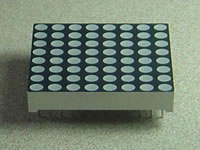
The Arduino Pi is a single board computer based on Arduino. The Arduino Pi has a six button keyboard known as GKOS , which is an chorded keyboard, and has an LED matrix based display. Right now, the LED matrix is a 5x5 LED matrix that scrolls. This was designed small but will later expand to maybe an 8x8 LED matrix and then 16x32 LED display. It has 4 digital pins for development using the Arduino platform. The scripting language is called Bitlash. I used Bitlash because it was easier to implement in the Arduino sketch than other programming languages.
Hardware
GKOS
With the 6 GKOS keys, directly connected to Arduino I/O pins, it is possible to type any text and enter most functions found on the PC keyboard (Alt, Ctrl, Tab...).
How to type

The GKOS Alphabet.
Letters G, K, O, S and W require two keys, and they also function as modifiers (shifts) changing the characters on other keys. For example, to press A, press the top left button. But to press H, press the top two buttons on the right ( the G key) and the top left button.
Pressing all 6 keys down toggles between numbers and letters. You get backspace by pressing the 3 keys on the left, and space by pressing the 3 keys on the right. The full character set can be found here.
GKOS Hardware

In the Arduino Pi, analog pins are used.
LED Matrix
The LED matrix is controlled using row-column scanning.
LED displays are often packaged as matrixes of LEDs arranged in rows of common anodes and columns of common cathodes, or the reverse. Here's a typical example of an 8x8 matrix, and its schematic:
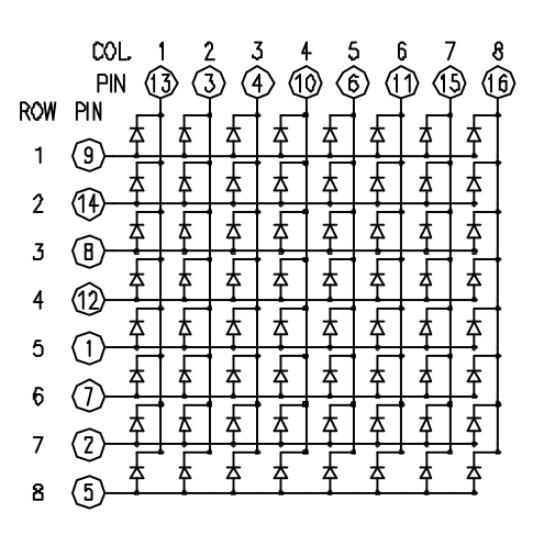
These can be very useful displays. To control a matrix, you connect both its rows and columns to your microcontroller. The columns are connected to the LEDs cathodes (see Figure 1), so a column needs to be high for any of the LEDs in that column to turn on. The rows are connected to the LEDs anodes, so the row needs to be low for an individual LED to turn on. If the row and the column are both high or both low, no voltage flows through the LED and it doesn’t turn on.
To control an individual LED, you set its column high and its row low. To control multiple LEDs in a row, you set the rows high, then take the column high, then set the lows row or high as appropriate; a low row will turn the corresponding LED on, and a high row will turn it off.
I used the code from the below link and leveraged it for a 5x5 matrix:
http://blog.duklabs.com/?p=133
Software
Bitlash
Bitlash is an open source interpreted language shell and embedded programming environment for Arduino. The Bitlash shell runs entirely on the Arduino and supports many of the familiar Arduino functions. Bitlash interprets commands you type on the serial port or send from your favorite PC-side programming environment. I have integrated Bitlash with the GKOS keypad so instead of using a serial port to enter commands, the GKOS keypad is used instead.

Bitlash Wiki:
https://github.com/billroy/bitlash/wiki/docindex
Bitlash website:
In my code, I use a command known as doCommand() which executes the command with the parentheses.
Extra pins
Due to the setup, there are extra pins that can be used for other functions like how a Raspberry Pi not only can be used as a computer but also as an electronics development board. However, the code to support this has not been developed.
More Information
For more information, go to