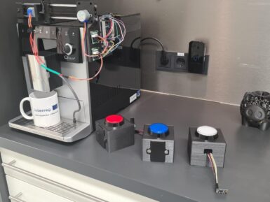
Getting started with the Arduino Primo This is a retired product. The Arduino Primo combines the processing power from the Nordic nRF52 processor, an Espressif ESP8266 for WiFi, as well as several on-board sensors and a battery charger. The nRF52 includes NFC (Near Field Communication) and Bluetooth® Smart. The sensors include an on-board button, LED and infrared receiver and transmitter. The Arduino Primo is programmed using the Arduino Software (IDE) , our Integrated Development Environment common to all our boards and running both online and offline. For more information on how to get started with the Arduino Software visit the Getting Started page . Use your Arduino Primo on the Arduino Web IDE All Arduino boards, including this one, work out-of-the-box on the Arduino Web Editor , you only need to install Arduino Create Agent to get started. The Arduino Web Editor is hosted online, therefore it will always be up-to-date with the latest features and support for all boards. Follow this simple guide to start coding on the browser and upload your sketches onto your board. Use your Arduino Primo on the Arduino Desktop IDE If you want to program your Arduino Primo while offline you need to install the Arduino Desktop IDE and add the Arduino NRF52 Core to it. This simple procedure is done selecting Tools menu , then Boards and last Boards Manager , as documented in the Arduino Boards Manager page. Installing Drivers for the Primo OSX and Windows (tested on XP, 7, Vista and 10) No driver installation is necessary for these operating system after core installation. Linux Before you can use the board on Linux machines you needs to execute the following script . Open your first sketch Open the LED blink example sketch: File > Examples >01.Basics > Blink . Select your board type and port You'll need to select the entry in the Tools > Board menu that corresponds to your Arduino board. Select the serial device of the board from the Tools | Serial Port menu. This is likely to be COM3 or higher ( COM1 and COM2 are usually reserved for hardware serial ports). To find out, you can disconnect your board and re-open the menu; the entry that disappears should be the Arduino board. Reconnect the board and select that serial port. Upload the program Now, simply click the "Upload" button in the environment. Wait a few seconds - you should see the RX and TX LEDs on the board flashing. If the upload is successful, the message "Done uploading." will appear in the status bar. A few seconds after the upload finishes, you should see the on-board LED L9 start to blink. If it does, congratulations! You've gotten your Primo board up-and-running. If you have problems, please see the troubleshooting suggestions . Tutorials Now that you have set up and programmed your Primo board, you may find inspiration in our Project Hub tutorial platform, or have a look to the tutorial pages that explain how to use the various features of your board. Please Read... First configuration Your Arduino Primo needs a first configuration to join your WiFi network and it allows you to enter the relevant information creating its own Access Point. Please execute the following procedure every time you bring Arduino Primo in a location where the WiFi network access needs to be reconfigured. Power the board and wait some time. Search the board in the network list, it has an ESSID like this: Arduino-Primo-xxxxxx . Connect your PC/MAC to the Arduino Primo AP: Open a browser and connect at this address: http://192.168.240.1/ This is the screen that it will appear: If you want to modify the hostname of the board then click on CHANGE from OVERVIEW menu or select the WiFi on the left menu and insert a new name under HOSTNAME field and after click on CHANGE . Connect the Arduino Primo to yours Access Point Router, selecting your network from WiFi Connection Menu. Type the correct password and click on CONNECT , as shown in the below image: Accept the alert message: When the board will be connected to the network, it will be shown the board ip address. Now, connect the PC to the same board network and try to access to the board inserting the ip address on the browser. After click on WiFi in the left menu and change the wifi configuration mode switching to STA MODE , as shown in the below image: Please note: It is important switching in STA MODE because so the board will be visible on the Arduino IDE and, furthermore, you will be able to protect it from possible attacks, since it will no longer be visible as open network. Now your Arduino Primo is ready. Hardware details Your Arduino Primo maintains full compatibility with UNO shields and offers you some new connectors and features. The following picture details the various hardware parts of the Primo board.. Following the LED_BUILTIN tradition, Arduino Primo has some other define that you can use in your sketches. Following, the complete list. LED_BUILTIN - Pin 9 - LED_BUILTIN is the L9 Led onboard BUZZER - Pin 35 - Manage the buzzer onboard USER1_BUTTON - Pin 34 - used also in some Low Power library functionalities USER2_BUTTON - Pin 44 - It isn't possible to attach an Interrupt USER2_LED - Pin 38 - User2 Led onboard BLE_LED - Pin 40 - Bluetooth® Low Energy led onboard Web panel functions details The Arduino Primo has a Web Panel that it can be reached in different ways: If the board isn't been configured yet, you can access inserting in browser this address: http://192.168.240.1/ In this case look at the First Configuration above to configure it. If the board is been correctly configured then you can insert the ip address (xxx.xxx.xxx.xxx) or the hostname (hostname.local/) from browser. The Web Panel has a simple menu that it is formed from two items: OVERVIEW and WIFI . The Home page of the Web Panel is the OVERVIEW . Here are shown all the information about the board, in particular the hostname, the network SSID, the Wifi address and the Wifi mode: Selecting the WIFI section, you can change the hostname of the board, typing the new name in the dedicated field and clicking on CHANGE button, as shown in the below image: It is possible to switch to STA MODE or STA+AP MODE clicking the specific button in the WIFI STATUS box. Please note: Keep in mind that it is advised to switch only in STA MODE because so the board will be visible on the Arduino IDE and you will be able to protect it from possible attacks, since it will no longer be visible as open network. Furthermore from the WIFI menu you can connect the board at your network, selecting it from WiFi Connections field, inserting the correct password and clicking on CONNECT button. In this section you can also choose if to use the DHCP or the Static IP, as shown in the picture: The text of the Arduino getting started guide is licensed under a Creative Commons Attribution-ShareAlike 3.0 License . Code samples in the guide are released into the public domain.
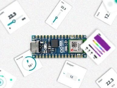
Getting started with the Arduino Uno WiFi This is a retired product. The Arduino Uno WiFi is an Arduino Uno with an integrated WiFi module. The board is based on the ATmega328P with an ESP8266 WiFi Module integrated. The ESP8266 WiFi Module is a self contained SoC with integrated TCP/IP protocol stack that can give access to your WiFi network (or the device can act as an access point). One useful feature of Uno WiFi is support for OTA (over-the-air) programming, either for transfer of Arduino sketches or WiFi firmware. The Arduino Uno WiFi is programmed using the Arduino Software (IDE) , our Integrated Development Environment common to all our boards and running both online and offline. For more information on how to get started with the Arduino Software visit the Getting Started page . Use your Arduino Uno WiFi on the Arduino Web IDE All Arduino boards, including this one, work out-of-the-box on the Arduino Web Editor , you only need to install Arduino Create Agent to get started. The Arduino Web Editor is hosted online, therefore it will always be up-to-date with the latest features and support for all boards. Follow this simple guide to start coding on the browser and upload your sketches onto your board. Use your Arduino Uno WiFi on the Arduino Desktop IDE If you want to program your Arduino Uno WiFi while offline you need to install the Arduino Desktop IDE . Full instructions on how to install it can be found in our Getting Started page . Installing Drivers for the Uno WiFi OSX The first time you plug an Uno WiFi into a Mac, the "Keyboard Setup Assistant" will launch. There's nothing to configure with the UNO WiFi, so you can close this window by clicking the red button in the top left of the window. Windows (tested on XP, 7, Vista and 10) At this point of this Getting Started guide you already have installed the drivers together with the Arduino Software (IDE) and the board will be recognized automatically. Linux There is no need to install drivers for Ubuntu 10.0.4 and later, but make sure port 5353 is not being blocked by a firewall. Open your first sketch Open the LED blink example sketch: File > Examples >01.Basics > Blink . Select your board type and port You'll need to select the entry in the Tools > Board menu that corresponds to your Arduino Uno WiFi board. Select the serial device of the board from the Tools | Serial Port menu. This is likely to be COM3 or higher ( COM1 and COM2 are usually reserved for hardware serial ports). To find out, you can disconnect your board and re-open the menu; the entry that disappears should be the Arduino Uno WiFi board. Reconnect the board and select that serial port. Upload the program Now, simply click the "Upload" button in the environment. Wait a few seconds - you should see the RX and TX LEDs on the board flashing. If the upload is successful, the message "Done uploading." will appear in the status bar. A few seconds after the upload finishes, you should see the on-board LED start to blink. If it does, congratulations! You've gotten your Uno WiFi board up-and-running for the USB programming. If you have problems, please see the troubleshooting suggestions . Programming via OTA This board allows you to upload your sketches over the air (OTA) using the WiFi connection. To get this method working, you need that your board is already connected to the same WiFi network to which your PC is connected. Please refer to the First Configuration chapter below to configure and connect the Arduino Uno WiFi to your WiFi network. Power the board using the USB cable and a 5V USB power supply or use an external power supply connected to the power connector.. Now the procedure to program the board via OTA is the same of that shown above but it differs only when you select the port. Here are all the steps.. Select your board type and port You'll need to select the entry in the Tools > Board menu that corresponds to your Arduino Uno WiFi board. Select the board from Tool>Port>Network ports menu it will appear a device as shown in the below image: Note: Be sure that the PC and the board are connected to the same network and that the board is in STA MODE, for more information see First Configuration below. Upload the program Now, simply click the "Upload" button in the environment. Wait a few seconds - you should see the RX and TX LEDs on the board flashing. If the upload is successful, the message "Done uploading." will appear in the status bar. A few seconds after the upload finishes, you should see the on-board LED start to blink. If it does, congratulations! You've gotten your Uno WiFi board up-and-running for the USB programming. If you have problems, please see the troubleshooting suggestions . Tutorials Now that you have set up and programmed your Uno WiFi board, you may find inspiration in our Project Hub tutorial platform, or have a look to the tutorial pages that explain how to use the various features of your board. We suggest that you visit the Ciao Library page that explains the peculiar functions of this and a few other Arduino boards like the Yún family and the Industrial 101.. Please Read... First configuration Your Arduino Uno WiFi needs a first configuration to join your WiFi network and it allows you to enter the relevant information creating its own Access Point. Please execute the following procedure every time you bring Arduino Uno WiFi in a location where the WiFi network access needs to be reconfigured. Power the board and wait some time. Search the board in the network list, it has an ESSID like this: Arduino-Uno-WiFi-xxxxxx . Connect your PC/MAC to the Arduino Uno WiFi AP: Open a browser and connect at this address: http://192.168.240.1/ This is the screen that it will appear: If you want to modify the hostname of the board then click on CHANGE from OVERVIEW menu or select the WiFi on the left menu and insert a new name under HOSTNAME field and after click on CHANGE . Connect the Arduino Uno WiFi to your AccessPoint Router, selecting your network from the WiFi Menu , insert the correct password and then click on CONNECT , as shown in the image below: When the board is connected to the network, the ip address will appear at the top of the panel: Now connect the PC to the same network to which the board is connected and try to access the board by inserting the ip address in the browser. Click on WiFi in the left menu and change the Wi-Fi configuration mode switching to STA MODE , as shown in the image below: Please note: It is important switching in STA MODE because so the board will be visible on the Arduino IDE and, furthermore, you will be able to protect it from possible attacks, since it will no longer be visible as open network. Now the "Mode Changed" message should appear at the top of the panel: Now, you can access the webpage using your hostname: http://hostname.local Your Arduino UNO WiFi is ready. Web panel functions details The Arduino UNO WiFi has a Web panel that it can be reached in different ways: If the board hasn't been configured yet, you can access it entering in the browser this link: http://192.168.240.1/ to configure the board read the First Configuration paragraph. If the board is been configured already for your WiFi network then you can insert the ip address (xxx.xxx.xxx.xxx) or the hostname(hostname.local/) from browser. The Web panel has a simple menu that it is formed from five items: OVERVIEW , SERIAL MONITOR , WIFI , CONNECTIVITY and DEBUG LOG . The Home page of the Web Panel corresponds to OVERVIEW menu, as shown in the image below: In the Overview is shown all the information about the configuration board: the hostname , the network SSID, Wifi address , Wifi mode and other details Clicking on SERIAL MONITOR displays a serial monitor, useful to display the results when you upload a sketch. Furthermore in this section it is possible to reset the microcontroller clicking on RESET μC button. Instead selecting from left menu the WIFI section, you can change the hostname simply typing the new hostname in the dedicated bar and after to click on CHANGE button, as shown in the below image: It is possible also to switch to STA MODE or STA+AP MODE clicking the specific button, but keep in mind that it is advised to switch only in STA MODE because so the board will be visible on the Arduino IDE and, furthermore, you will be able to protect it from possible attacks, since it will no longer be visible as open network. It is possible to connect the board to a network selecting it, inserting the correct password and clicking on CONNECTbutton. In this section you can also choose if to use the DHCP or the Static IP, as shown in the picture: In the CONNECTIVITY section you can enable the connection services for example the client MQTT and the SLIP: Finally in the DEBUG LOG it is shown the debug log and it is possible to reboot the WiFi clicking the WiFiREBOOTbutton: See also Firmware updater How to change Arduino Uno WiFi Firmware The text of the Arduino getting started guide is licensed under a Creative Commons Attribution-ShareAlike 3.0 License . Code samples in the guide are released into the public domain.
How to change the firmware of Arduino UNO WiFi There are four different ways to change or upgrade the firmware on your Arduino UNO WiFi: burn the firmware using UNO WiFi Firmware Updater tool (for all O.S. via Serial); burn the firmware using Arduino Software (IDE) 1.7.x (for all O.S. via OTA ); burn the firmware using ESP recovery (for all O.S. via Serial); burn the firmware using ESP Flash Download tool for Windows user (Only Windows via Serial). All these ways are shown in below paragraphs. Burn the firmware using UNO WiFi Firmware Updater tool If you are using the Arduino 1.8.x or later then you can upgrade the Esp firmware using the UNO WiFi Firmware Updater tool . The complete guide is in this link . Note: This procedure is recommended for all Operating System and it is usable via serial. Burn the Firmware using the Arduino Software (IDE) If you want burn the firmware using the file into Arduino Software (IDE) 1.7.x , then continue to follow the guide, if instead you are using the Arduino Software (IDE) 1.8.x then follow the Arduino UNO WiFi Firmware Updater guide . Note: This procedure is reccommended for all Operating System and it is usable only via OTA . Download the latest Arduino Software (IDE) version. Click here. Launch the Arduino Software (IDE). Plug the Arduino UNO WiFi to PC. Select the board: Arduino UNO WiFi from Tools>Board menu. Select the Port from Tools > Ports > Network ports menu. Select the Programmer from Tools > Programmer > ESP8266 Over The Air menu. Click on Burn Bootloader from Tools menu. Burn the firmware using EspRecovery This procedure is recommended for all Operating System and it is usable only via Serial . 1 - First you must upload the EspRecovery sketch on your Arduino UNO WiFi: Connect the Arduino UNO WiFi to PC with a USB cable. Open the Arduino Software (IDE). Select the correspondent port and board. Upload the ESPRecovery sketch from File > Examples>Arduino UNO WiFI > Tools menu of Arduino Software (IDE): 2 - Enter the board in bootloader mode: Disconnect the Arduino Uno WiFi Reconnect the board while pressing the ESP B/L button. 3 - Open your terminal as Administrator. 4 - Download the ESPtool , you can download from here or you can use the command: sudo pip install esptool 5 - Test the esptool, for example, inserting the below command to read the MAC address: python esptool.py -p your port -b baudrate read_mac Set the baudrate at 9600 . For linux user, for example, the port will be /dev/ttyACM0: sudo python esptool.py -p /dev/ttyACM0 -b 9600 read_mac For Mac user, for example, the port will be /dev/tty.usbmodem1411: sudo python esptool.py -p /dev/tty.usbmodem1411 -b 9600 read_mac For Windows user: for example in case that the tools is in * * \Users\XXXX\Desktop\esptool\esptool * * folder and the COM is 30: python \User\XXXX\Desktop\esptool\esptool\esptool.py -p COM30 -b 9600 read_mac If it appears on your MAC terminal, then continue the procedure: Connecting... MAC: 18:fe:34:10:e2:85 7 - Use this command to write the firmware but PAY ATTENTION to set the correct path and insert your correspondent port: For Windows user: for example in case that the tools is in \Users\XXXX\Desktop\esptool\esptool * * folder and the COM is 30 * * : 8 - Wait some minutes that the process ends Note: You can find the updated user1.bin file directly into Arduino Software (IDE), here the path: arduino-1.7.x\hardware\arduino\avr\firmwares\ esp8266 \unowifi\firmware_arduino_ esp8266 _20xx_xx_xx_file1.bin Burn the firmware using ESP Flash download tool If you are a Windows user and you want to upgrade the firmware using a baudrate higher than 9600 then follow the procedure below: Note: This method allows to burn the firmware quickly (baudrate to 115200) but it needs an USB2Serial and some welding. 1 - First you must upload the Blink sketch on your Arduino UNO WiFi: Connect the Arduino UNO WiFi to your PC with a USB cable. Open the Arduino Software (IDE), you can download it here. Select the correspondent port and board. Upload the Blink sketch from File > Examples > Basics menu. 2 - Create a jumper between TP_GPIOESP test point and Ground , as shown in the image below: 3 - Connect the board to the USB2Serial : Using some jumpers follow these connections: USB2SerialArduino Uno WiFiRXRXTXTXGNDGND Connect the USB2Serial converter to your PC. 4 - Put the board in bootloader mode: Disconnect the Arduino Uno WiFi Reconnect the board while pressing the ESP B/L button. 5 - Open the ESP FLASH DOWNLOAD TOOL , you can download it from here Δ . Extract it; Click on flash_download_tool_v1.2_150512.exe. 6 - Setting the the esptool : Select the first row and insert the boot.bin_rep file and set the address: 0x00000. Select the second row and insert the user1.bin file and set the address: 0x40000. Select the third row and insert the esp_init_data_default.bin_rep fileand set the address: 0x7C000. Select the quarter row and insert the blank.bin file and set the address: 0x7E000, as shown in the picture. Note: You can find the updated user1.bin file directly into Arduino Software (IDE) , here the path: arduino-1.7.x\hardware\arduino\avr\firmwares\ esp8266 \unowifi\firmware_arduino_ esp8266 _20xx_xx_xx_file1.bin Select the correspondent USB2Serial COM . Setting the baudrate to 115200 . 7 - Execute the Firmware writing. Click on START Wait the ending of the process; Finish will appear when done, as shown in the image below. 8 - Now remove the jumper between TP_GPIOESP and Ground . See also Getting started with Arduino Uno WiFi Firmware updater The text of the Arduino getting started guide is licensed under a Creative Commons Attribution-ShareAlike 3.0 License . Code samples in the guide are released into the public domain.
Getting Started with the MKR Connector Carrier The MKR Connector Carrier allows any MKR board to use the range of modules and devices that use the Grove Connector , developer by Seeed Studio and now a de facto standard for solderless connection of analog and digital modules. PLEASE NOTE: a limited number of boards have a wrong labeling on the solder side. Please refer to the current image for the correct labelling. The component side labels are correct on all the boards. Please refer to them for your connections. Power supply All the I/Os are supplied at 5V and the carrier provides the proper 5V to 3.3V level shifting. The board has a buck converter that can be supplied with an external voltage from 7V to 16V connected to the VIN of the screw terminal block. The buck converter supplies the MKR board that provides the 5V and the 3.3V output that can also be found on the screw terminal blocks. Modules and cables The Grove modules have a standard four pins connector and usually the cable that comes with them has four standard colors: pin 1 - Yellow (for example, SCL on I2C Grove Connectors) pin 2 - White (for example, SDA on I2C Grove Connectors) pin 3 - Red - VCC on all Grove Connectors pin 4 - Black - GND on all Grove Connectors A0-A6 Analog input An Grove Analog connector consists of the standard four lines coming into the Grove plug. The two signal lines are generically called A0 and A1. Most modules only use A0. Often base units will have the first connector called A0 and the second called A1 and they will be wired A0/A1 and then A1/A2, etc. Pin Function Notes pin1 An Primary analog input pin2 An+1 Secondary analog input pin3 VCC Power to module 5V/3.3V pin4 GND Ground Input only (analog or digital) with a maximum allowed voltage of 5V. The 5V to supplied the sensor is provided by the board. The last connector labeled A5 A6 is a connector that wires two analog inputs into a single connector according to the grove connector specifications. If a single input has to be used the wired one is A5. D0-D6 Digital input output A digital Grove connector consists of the standard four lines coming into the Grove plug. The two signal lines are generically called D0 and D1. Most modules only use D0, but some do (like the LED Bar Grove display) use both. Often base units will have the first connector called D0 and the second called D1 and they will be wired D0/D1 and then D1/D2, etc. Pin Function Notes pin1 Dn Primary digital I/O pin2 Dn+1 Secondary digital I/O pin3 VCC Power to module 5V/3.3V pin4 GND Ground I/O digital with a maximum allowed voltage of 5V. The 5V to supplied the sensor is provided by the board. The last connector labeled D5 D6 is a connector that wires two digital I/O into a single connector according to the grove connector specifications. If a single I/O has to be used the wired one is D5. Serial The Serial connector on the board is wired to the MKR board according to the grove connector specifications. The Grove UART module is a specialized version of a Grove Digital Module. It uses both Pin 1 and Pin 2 for the serial input and transmit. The Grove UART plug is labeled from the base unit point of view. In other words, Pin 1 is the RX line (which the base unit uses to receive data, so it is an input) where Pin 2 is the TX line (which the base unit uses to transmit data to the Grove module). Pin Function Notes pin1 RX Serial receive pin2 TX Serial transmit pin3 VCC Power to module 5V/3.3V pin4 GND Ground TWI - I2C The TWI connector on the board is wired to the MKR board according to the grove connector specifications. There are many types of I2C Grove sensors available. Most are 5V/3.3V devices, but there are a few that are only 3.3V or 5.0V. You need to check the specifications. The Grove I2C connector has the standard layout. Pin 1 is the SCL signal and Pin 2 is the SDA signal. Power and Ground are the same as the other connectors. This is another special version of the Grove Digital Connector. In fact, often the I2C bus on a controller (like the ESP8266 , Raspberry Pi and the Arduino) just uses Digital I/O pins to implement the I2C bus. The pins on the Raspberry Pi and Arduino are special with hardware support for the I2C bus. Pin Function Notes pin1 SCL I2C Clock pin2 SDA I2C Data pin3 VCC Power to module 5V/3.3V pin4 GND Ground See also Show humidity and temperature on an OLED screen The text of the Arduino getting started guide is licensed under a Creative Commons Attribution-ShareAlike 3.0 License . Code samples in the guide are released into the public domain.
Blynk_Esp8266AT_WMSimple WiFiManager for Blynk with MultiWiFi Credentials, for Mega, SAM DUE, SAMD21, SAMD51, nRF52, STM32F/L/H/G/WB/MP1, Teensy, RP2040-based RASPBERRY_PI_PICO, etc. boards running ESP8266/ESP32-AT shields. Configuration data saved in EEPROM, EEPROM-emulated FlashStorage_STM32 or FlashStorage_SAMD, SAM-DUE DueFlashStorage or nRF52/TP2040 LittleFS.

'%20fill='white'/%3e%3cpath%20d='M34.2361%2026.458C34.8709%2027.0929%2034.8709%2028.1205%2034.2361%2028.7553L26.1924%2036.7991L24.1443%2034.751L31.2527%2027.6426L24.1084%2020.4983L26.1924%2018.4143L34.2361%2026.458Z'%20fill='%23374146'/%3e%3c/svg%3e)
 See all results