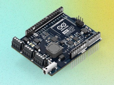
Getting started with the Arduino Uno WiFi Rev2 The Arduino Uno WiFi Rev2 is an Arduino Uno with an integrated WiFi module. The board is based on the Microchip MEGA4809 with an ESP32 u-blox NINA-W13 WiFi Module integrated. The NINA-W13 Module is a self contained SoC with integrated TCP/IP protocol stack that can give access to your WiFi network (or the device can act as an access point). The Arduino Uno WiFi Rev2 is programmed using the Arduino Software (IDE) , our Integrated Development Environment common to all our boards and running both online and offline. For more information on how to get started with the Arduino Software visit the Getting Started page . Use your Arduino Uno WiFi Rev2 on the Arduino Web IDE All Arduino boards, including this one, work out-of-the-box on the Arduino Web Editor , you only need to install Arduino Create Agent to get started. The Arduino Web Editor is hosted online, therefore it will always be up-to-date with the latest features and support for all boards. Follow this simple guide to start coding on the browser and upload your sketches onto your board. Use your Arduino Uno WiFi Rev2 on the Arduino Desktop IDE If you want to program your Arduino Uno WiFi Rev2 while offline you need to install the Arduino Desktop IDE . Full instructions on how to install it can be found in our Getting Started page . You will need to add the Arduino megaAVR Core to the Arduino IDE. This simple procedure is done selecting Tools menu , then Boards and last Boards Manager , as documented in the Arduino Boards Manager page. Installing Drivers for the Uno WiFi macOS No drivers are needed for the Arduino UNO WiFi Rev2 on macOS. Windows (tested on XP, 7, Vista and 10) At this point of this Getting Started guide you already have installed the drivers together with the Arduino Software (IDE) and the board will be recognized automatically. Linux There is no need to install drivers for Ubuntu 10.0.4 and later, but make sure port 5353 is not being blocked by a firewall. Users with Linux need to run this code in the terminal: ~/.arduino15/packages/ arduino /hardware/megaavr/1.8.1/scripts/create_dfu_udev_rule You need to be admin on the computer to do so. Open your first sketch Open the LED blink example sketch: File > Examples >01.Basics > Blink . Select your board type and port You'll need to select the entry in the Tools > Board menu that corresponds to your Arduino Uno WiFi Rev2 board. Select the serial device of the board from the Tools | Serial Port menu. This is likely to be COM3 or higher ( COM1 and COM2 are usually reserved for hardware serial ports). To find out, you can disconnect your board and re-open the menu; the entry that disappears should be the Arduino Uno WiFi Rev2 board. Reconnect the board and select that serial port. Upload the program Now, simply click the "Upload" button in the environment. Wait a few seconds - you should see the green progress bar on the right of the status bar. If the upload is successful, the message "Done uploading." will appear on the left in the status bar. A few seconds after the upload finishes, you should see the on-board LED start to blink. If it does, congratulations! You've gotten your Uno WiFi board up-and-running for the USB programming. If you have problems, please see the troubleshooting suggestions . Tutorials Now that you have set up and programmed your Uno WiFi board, you may find inspiration in our Project Hub tutorial platform, or have a look to the tutorial pages that explain how to use the various features of your board. We suggest that you visit the WiFi Nina Library page that explains the network functions of this board. Please Read... This board uses the new Microchip MEGA4809 microcontroller that has a different memory layout compared to the usual ATmega 328P. You now have 48K of Flash memory, 6K of RAM and 256 bytes of EEPROM, therefore you have more Flash and more memory than the Arduino UNO (16K Flash and 2K RAM). The programming of the MEGA4809 happens through an ATmega 32U4 programmed with the mDBG code and creates a virtual COM port when connected to a PC. Serial ports The Arduino Uno WiFi Rev. 2 has 3 hardware serial ports. Serial is connected to the USB interface, Serial1 is connected to Pin 0 (RX) and 1 (TX) , Serial 2 is connected to the u-blox NINA-W13 module. This allows the usage of pins 0 and 1 without issues: on the original Arduino UNO , the usage of Pins 0 and 1 disrupts the sketch upload. SPI The SPI interface is available on the ICSP connector with the usual layout for MISO, MOSI, SCK and CS. The IMU and the WiFi module are connected to the SPI bus and have individuale and dedicated pins for Chip Select (CS) I2C The I2C interface is available on the SDA and SCL pins. Unlike the classic Arduino Uno , these pins are not alternatives to pins A4 and A5. This means you are still free to use the Uno WiFi Rev2's A4 and A5 for anything you like when an I2C device is connected to SDA and SCL. Analog The new core has 5 PWM pins and the pin 11 doesn't support PWM. The resolution of the 6 A/D pins is the usual, with 10 bits and values from 0 to 1023. RGB LED Close to the Nina module and the ICSP connector there is a square RGB SMD LED. This LED is directly connected to the NINA-W13 WiFi module and it is driven by the module itself. It will be used for future applications and developments. Integrated IMU On the SPI bus, with a dedicated CS connection (pin D30 or SPIIMU_SS) and a dedicated interrupt pin (SPIIMU_INT), the Arduino UNO WiFi Rev.2 has a LSM6DS IMU with 3-axis accelerometer and 3-axis gyroscope. This chip, made by ST Microelectronics, is a standard component that you can use with our own library Arduino _LSM6DS3 . To get the library, you can use our Library Manager available in the Arduino Software (IDE) . The library contains two examples to show you how to read acceleration and rotational speed. Interrupts The new MEGA4809 microcontroller allows you to attach any digital pin to an interrupt, therefore you may have as many Interrupt Service Routines (ISR) as the available digital pins. You still define the interrupts with the usual function attachInterrupt(digitalPinToInterrupt(pin), ISR, mode); . Please refer to the attachInterrupt() page for further details. Note: the WiFi antenna built in in the U-blox NINA-W13 module is made for embedded products and should NOT be touched. Applying pressure or force on it could cause damage. Be very careful when you detach shields on this board because you may pull the WiFi antenna. The text of the Arduino getting started guide is licensed under a Creative Commons Attribution-ShareAlike 3.0 License . Code samples in the guide are released into the public domain.
Arduino UNO WiFi firmware updater This tutorial will guide you in the process of updating the firmware of your Arduino UNO WiFi board. Hardware required Arduino UNO WiFi Circuit Connect the board at the USB port of your computer ready with Arduino Software (IDE) 1.8.0 or later. UNO WiFi Firmware updater procedure To simplify the process, we have prepared a tool - UNO WiFiFirmwareUpdater - available in Arduino IDE 1.8.0 or later. Follow these steps to enable this tools into Arduino software: Download the tool here . Create a folder called tools into the sketchbook directory (normally in Documents > Arduino ). Extract it. Now: Launch the Arduino Software (IDE) 1.8.0 or later. Connect the board to PC. Select the Arduino UNO WiFi as board in the Tools > Board menu . Select the corresponding serial port in the Tools > Port menu . Upload the ESP Recovery sketch . It is into the UNOWiFiDev.Edition Library. Download it from Library Manager . Put the board in DFU mode, keeping pressed the ESP B/L button and connect the board to PC Select the UnoWiFi Firmware Updater from the Tools menu. Click on Refresh list if the port is not listed. Select the corresponding port. Click on Test connection . Select from windows menu the ESP firmware requested. Click on Update Firmware . Wait the end of process. Warning: The process could last several minutes. See also Getting started with Arduino Uno WiFi How to change the firmware The text of the Arduino getting started guide is licensed under a Creative Commons Attribution-ShareAlike 3.0 License . Code samples in the guide are released into the public domain.
How to change the firmware of Arduino UNO WiFi There are four different ways to change or upgrade the firmware on your Arduino UNO WiFi: burn the firmware using UNO WiFi Firmware Updater tool (for all O.S. via Serial); burn the firmware using Arduino Software (IDE) 1.7.x (for all O.S. via OTA ); burn the firmware using ESP recovery (for all O.S. via Serial); burn the firmware using ESP Flash Download tool for Windows user (Only Windows via Serial). All these ways are shown in below paragraphs. Burn the firmware using UNO WiFi Firmware Updater tool If you are using the Arduino 1.8.x or later then you can upgrade the Esp firmware using the UNO WiFi Firmware Updater tool . The complete guide is in this link . Note: This procedure is recommended for all Operating System and it is usable via serial. Burn the Firmware using the Arduino Software (IDE) If you want burn the firmware using the file into Arduino Software (IDE) 1.7.x , then continue to follow the guide, if instead you are using the Arduino Software (IDE) 1.8.x then follow the Arduino UNO WiFi Firmware Updater guide . Note: This procedure is reccommended for all Operating System and it is usable only via OTA . Download the latest Arduino Software (IDE) version. Click here. Launch the Arduino Software (IDE). Plug the Arduino UNO WiFi to PC. Select the board: Arduino UNO WiFi from Tools>Board menu. Select the Port from Tools > Ports > Network ports menu. Select the Programmer from Tools > Programmer > ESP8266 Over The Air menu. Click on Burn Bootloader from Tools menu. Burn the firmware using EspRecovery This procedure is recommended for all Operating System and it is usable only via Serial . 1 - First you must upload the EspRecovery sketch on your Arduino UNO WiFi: Connect the Arduino UNO WiFi to PC with a USB cable. Open the Arduino Software (IDE). Select the correspondent port and board. Upload the ESPRecovery sketch from File > Examples> Arduino UNO WiFI > Tools menu of Arduino Software (IDE): 2 - Enter the board in bootloader mode: Disconnect the Arduino Uno WiFi Reconnect the board while pressing the ESP B/L button. 3 - Open your terminal as Administrator. 4 - Download the ESPtool , you can download from here or you can use the command: sudo pip install esptool 5 - Test the esptool, for example, inserting the below command to read the MAC address: python esptool.py -p your port -b baudrate read_mac Set the baudrate at 9600 . For linux user, for example, the port will be /dev/ttyACM0: sudo python esptool.py -p /dev/ttyACM0 -b 9600 read_mac For Mac user, for example, the port will be /dev/tty.usbmodem1411: sudo python esptool.py -p /dev/tty.usbmodem1411 -b 9600 read_mac For Windows user: for example in case that the tools is in * * \Users\XXXX\Desktop\esptool\esptool * * folder and the COM is 30: python \User\XXXX\Desktop\esptool\esptool\esptool.py -p COM30 -b 9600 read_mac If it appears on your MAC terminal, then continue the procedure: Connecting... MAC: 18:fe:34:10:e2:85 7 - Use this command to write the firmware but PAY ATTENTION to set the correct path and insert your correspondent port: For Windows user: for example in case that the tools is in \Users\XXXX\Desktop\esptool\esptool * * folder and the COM is 30 * * : 8 - Wait some minutes that the process ends Note: You can find the updated user1.bin file directly into Arduino Software (IDE), here the path: arduino -1.7.x\hardware\ arduino \avr\firmwares\esp8266\unowifi\firmware_ arduino _esp8266_20xx_xx_xx_file1.bin Burn the firmware using ESP Flash download tool If you are a Windows user and you want to upgrade the firmware using a baudrate higher than 9600 then follow the procedure below: Note: This method allows to burn the firmware quickly (baudrate to 115200) but it needs an USB2Serial and some welding. 1 - First you must upload the Blink sketch on your Arduino UNO WiFi: Connect the Arduino UNO WiFi to your PC with a USB cable. Open the Arduino Software (IDE), you can download it here. Select the correspondent port and board. Upload the Blink sketch from File > Examples > Basics menu. 2 - Create a jumper between TP_GPIOESP test point and Ground , as shown in the image below: 3 - Connect the board to the USB2Serial : Using some jumpers follow these connections: USB2SerialArduino Uno WiFiRXRXTXTXGNDGND Connect the USB2Serial converter to your PC. 4 - Put the board in bootloader mode: Disconnect the Arduino Uno WiFi Reconnect the board while pressing the ESP B/L button. 5 - Open the ESP FLASH DOWNLOAD TOOL , you can download it from here Δ . Extract it; Click on flash_download_tool_v1.2_150512.exe. 6 - Setting the the esptool : Select the first row and insert the boot.bin_rep file and set the address: 0x00000. Select the second row and insert the user1.bin file and set the address: 0x40000. Select the third row and insert the esp_init_data_default.bin_rep fileand set the address: 0x7C000. Select the quarter row and insert the blank.bin file and set the address: 0x7E000, as shown in the picture. Note: You can find the updated user1.bin file directly into Arduino Software (IDE) , here the path: arduino -1.7.x\hardware\ arduino \avr\firmwares\esp8266\unowifi\firmware_ arduino _esp8266_20xx_xx_xx_file1.bin Select the correspondent USB2Serial COM . Setting the baudrate to 115200 . 7 - Execute the Firmware writing. Click on START Wait the ending of the process; Finish will appear when done, as shown in the image below. 8 - Now remove the jumper between TP_GPIOESP and Ground . See also Getting started with Arduino Uno WiFi Firmware updater The text of the Arduino getting started guide is licensed under a Creative Commons Attribution-ShareAlike 3.0 License . Code samples in the guide are released into the public domain.
Getting started with the Arduino Uno WiFi This is a retired product. The Arduino Uno WiFi is an Arduino Uno with an integrated WiFi module. The board is based on the ATmega328P with an ESP8266WiFi Module integrated. The ESP8266WiFi Module is a self contained SoC with integrated TCP/IP protocol stack that can give access to your WiFi network (or the device can act as an access point). One useful feature of Uno WiFi is support for OTA (over-the-air) programming, either for transfer of Arduino sketches or WiFi firmware. The Arduino Uno WiFi is programmed using the Arduino Software (IDE) , our Integrated Development Environment common to all our boards and running both online and offline. For more information on how to get started with the Arduino Software visit the Getting Started page . Use your Arduino Uno WiFi on the Arduino Web IDE All Arduino boards, including this one, work out-of-the-box on the Arduino Web Editor , you only need to install Arduino Create Agent to get started. The Arduino Web Editor is hosted online, therefore it will always be up-to-date with the latest features and support for all boards. Follow this simple guide to start coding on the browser and upload your sketches onto your board. Use your Arduino Uno WiFi on the Arduino Desktop IDE If you want to program your Arduino Uno WiFi while offline you need to install the Arduino Desktop IDE . Full instructions on how to install it can be found in our Getting Started page . Installing Drivers for the Uno WiFi OSX The first time you plug an Uno WiFi into a Mac, the "Keyboard Setup Assistant" will launch. There's nothing to configure with the UNO WiFi, so you can close this window by clicking the red button in the top left of the window. Windows (tested on XP, 7, Vista and 10) At this point of this Getting Started guide you already have installed the drivers together with the Arduino Software (IDE) and the board will be recognized automatically. Linux There is no need to install drivers for Ubuntu 10.0.4 and later, but make sure port 5353 is not being blocked by a firewall. Open your first sketch Open the LED blink example sketch: File > Examples >01.Basics > Blink . Select your board type and port You'll need to select the entry in the Tools > Board menu that corresponds to your Arduino Uno WiFi board. Select the serial device of the board from the Tools | Serial Port menu. This is likely to be COM3 or higher ( COM1 and COM2 are usually reserved for hardware serial ports). To find out, you can disconnect your board and re-open the menu; the entry that disappears should be the Arduino Uno WiFi board. Reconnect the board and select that serial port. Upload the program Now, simply click the "Upload" button in the environment. Wait a few seconds - you should see the RX and TX LEDs on the board flashing. If the upload is successful, the message "Done uploading." will appear in the status bar. A few seconds after the upload finishes, you should see the on-board LED start to blink. If it does, congratulations! You've gotten your Uno WiFi board up-and-running for the USB programming. If you have problems, please see the troubleshooting suggestions . Programming via OTA This board allows you to upload your sketches over the air (OTA) using the WiFi connection. To get this method working, you need that your board is already connected to the same WiFi network to which your PC is connected. Please refer to the First Configuration chapter below to configure and connect the Arduino Uno WiFi to your WiFi network. Power the board using the USB cable and a 5V USB power supply or use an external power supply connected to the power connector.. Now the procedure to program the board via OTA is the same of that shown above but it differs only when you select the port. Here are all the steps.. Select your board type and port You'll need to select the entry in the Tools > Board menu that corresponds to your Arduino Uno WiFi board. Select the board from Tool>Port>Network ports menu it will appear a device as shown in the below image: Note: Be sure that the PC and the board are connected to the same network and that the board is in STA MODE, for more information see First Configuration below. Upload the program Now, simply click the "Upload" button in the environment. Wait a few seconds - you should see the RX and TX LEDs on the board flashing. If the upload is successful, the message "Done uploading." will appear in the status bar. A few seconds after the upload finishes, you should see the on-board LED start to blink. If it does, congratulations! You've gotten your Uno WiFi board up-and-running for the USB programming. If you have problems, please see the troubleshooting suggestions . Tutorials Now that you have set up and programmed your Uno WiFi board, you may find inspiration in our Project Hub tutorial platform, or have a look to the tutorial pages that explain how to use the various features of your board. We suggest that you visit the Ciao Library page that explains the peculiar functions of this and a few other Arduino boards like the Yún family and the Industrial 101.. Please Read... First configuration Your Arduino Uno WiFi needs a first configuration to join your WiFi network and it allows you to enter the relevant information creating its own Access Point. Please execute the following procedure every time you bring Arduino Uno WiFi in a location where the WiFi network access needs to be reconfigured. Power the board and wait some time. Search the board in the network list, it has an ESSID like this: Arduino-Uno -WiFi-xxxxxx . Connect your PC/MAC to the Arduino Uno WiFi AP: Open a browser and connect at this address: http://192.168.240.1/ This is the screen that it will appear: If you want to modify the hostname of the board then click on CHANGE from OVERVIEW menu or select the WiFi on the left menu and insert a new name under HOSTNAME field and after click on CHANGE . Connect the Arduino Uno WiFi to your AccessPoint Router, selecting your network from the WiFi Menu , insert the correct password and then click on CONNECT , as shown in the image below: When the board is connected to the network, the ip address will appear at the top of the panel: Now connect the PC to the same network to which the board is connected and try to access the board by inserting the ip address in the browser. Click on WiFi in the left menu and change the Wi-Fi configuration mode switching to STA MODE , as shown in the image below: Please note: It is important switching in STA MODE because so the board will be visible on the Arduino IDE and, furthermore, you will be able to protect it from possible attacks, since it will no longer be visible as open network. Now the "Mode Changed" message should appear at the top of the panel: Now, you can access the webpage using your hostname: http://hostname.local Your Arduino UNO WiFi is ready. Web panel functions details The Arduino UNO WiFi has a Web panel that it can be reached in different ways: If the board hasn't been configured yet, you can access it entering in the browser this link: http://192.168.240.1/ to configure the board read the First Configuration paragraph. If the board is been configured already for your WiFi network then you can insert the ip address (xxx.xxx.xxx.xxx) or the hostname(hostname.local/) from browser. The Web panel has a simple menu that it is formed from five items: OVERVIEW , SERIAL MONITOR , WIFI , CONNECTIVITY and DEBUG LOG . The Home page of the Web Panel corresponds to OVERVIEW menu, as shown in the image below: In the Overview is shown all the information about the configuration board: the hostname , the network SSID, Wifi address , Wifi mode and other details Clicking on SERIAL MONITOR displays a serial monitor, useful to display the results when you upload a sketch. Furthermore in this section it is possible to reset the microcontroller clicking on RESET μC button. Instead selecting from left menu the WIFI section, you can change the hostname simply typing the new hostname in the dedicated bar and after to click on CHANGE button, as shown in the below image: It is possible also to switch to STA MODE or STA+AP MODE clicking the specific button, but keep in mind that it is advised to switch only in STA MODE because so the board will be visible on the Arduino IDE and, furthermore, you will be able to protect it from possible attacks, since it will no longer be visible as open network. It is possible to connect the board to a network selecting it, inserting the correct password and clicking on CONNECTbutton. In this section you can also choose if to use the DHCP or the Static IP, as shown in the picture: In the CONNECTIVITY section you can enable the connection services for example the client MQTT and the SLIP: Finally in the DEBUG LOG it is shown the debug log and it is possible to reboot the WiFi clicking the WiFiREBOOTbutton: See also Firmware updater How to change Arduino Uno WiFi Firmware The text of the Arduino getting started guide is licensed under a Creative Commons Attribution-ShareAlike 3.0 License . Code samples in the guide are released into the public domain.
Getting Started with Arduino UNO This document explains how to connect your Uno board to the computer and upload your first sketch. The Arduino Uno is programmed using the Arduino Software (IDE) , our Integrated Development Environment common to all our boards and running both online and offline. For more information on how to get started with the Arduino Software visit the Getting Started page . Use your Arduino Uno on the Arduino Web IDE All Arduino boards, including this one, work out-of-the-box on the Arduino Web Editor , you only need to install Arduino Create Agent to get started. The Arduino Web Editor is hosted online, therefore it will always be up-to-date with the latest features and support for all boards. Follow this simple guide to start coding on the browser and upload your sketches onto your board. Use your Arduino Uno on the Arduino Desktop IDE If you want to program your Arduino Uno while offline you need to install the Arduino Desktop IDE The Uno is programmed using the Arduino Software (IDE), our Integrated Development Environment common to all our boards. Before you can move on, you must have installed the Arduino Software (IDE) on your PC, as explained in the home page of our Getting Started . Connect your Uno board with an A B USB cable; sometimes this cable is called a USB printer cable The USB connection with the PC is necessary to program the board and not just to power it up. The Uno automatically draw power from either the USB or an external power supply. Connect the board to your computer using the USB cable. The green power LED (labelled PWR ) should go on. Install the board drivers If you used the Installer, Windows - from XP up to 10 - will install drivers automatically as soon as you connect your board. If you downloaded and expanded the Zip package or, for some reason, the board wasn't properly recognized, please follow the procedure below. Click on the Start Menu, and open up the Control Panel. While in the Control Panel, navigate to System and Security. Next, click on System. Once the System window is up, open the Device Manager. Look under Ports (COM & LPT). You should see an open port named " Arduino UNO (COMxx)". If there is no COM & LPT section, look under "Other Devices" for "Unknown Device". Right click on the " Arduino UNO (COmxx)" port and choose the "Update Driver Software" option. Next, choose the "Browse my computer for Driver software" option. Finally, navigate to and select the driver file named " arduino .inf" , located in the "Drivers" folder of the Arduino Software download (not the "FTDI USB Drivers" sub-directory). If you are using an old version of the IDE (1.0.3 or older), choose the Uno driver file named " Arduino UNO .inf" Windows will finish up the driver installation from there. See also: step-by-step screenshots for installing the Uno under Windows XP . Open your first sketch Open the LED blink example sketch: File > Examples >01.Basics > Blink . Select your board type and port You'll need to select the entry in the Tools > Board menu that corresponds to your Arduino board. Select the serial device of the board from the Tools | Serial Port menu. This is likely to be COM3 or higher ( COM1 and COM2 are usually reserved for hardware serial ports). To find out, you can disconnect your board and re-open the menu; the entry that disappears should be the Arduino board. Reconnect the board and select that serial port. Upload the program Now, simply click the "Upload" button in the environment. Wait a few seconds - you should see the RX and TX leds on the board flashing. If the upload is successful, the message "Done uploading." will appear in the status bar. A few seconds after the upload finishes, you should see the pin 13 (L) LED on the board start to blink (in orange). If it does, congratulations! You've gotten Arduino up-and-running. If you have problems, please see the troubleshooting suggestions . Learn more on the Desktop IDE See this tutorial for a generic guide on the Arduino IDE with a few more infos on the Preferences, the Board Manager, and the Library Manager. Tutorials Now that you have set up and programmed your Uno board, you may find inspiration in our Project Hub tutorial platform or have a look to the tutorial pages that explain how to use the various features of your board. examples for using various sensors and actuators reference for the Arduino language

 See all results
'%20fill='white'/%3e%3cpath%20d='M34.2361%2026.458C34.8709%2027.0929%2034.8709%2028.1205%2034.2361%2028.7553L26.1924%2036.7991L24.1443%2034.751L31.2527%2027.6426L24.1084%2020.4983L26.1924%2018.4143L34.2361%2026.458Z'%20fill='%23374146'/%3e%3c/svg%3e)