Update 2 May 2014 Modified mouse.txt setup, to accommodate for Intellimouse vertical wheel (scroll)
Update 18 Jul 2009 Added ps2dev library for being a ps2 device
Update 12 Oct 2008 New version of the library updated that works with Arduino 0012.
Update 29 Sept 2008 This library has issues with Arduino 0012, we are looking into it.
Update 29 Jan 2008 All the ps2 functions have been put into a library, with examples of how to use it for a keyboard or a mouse. Get the ps2.zip file (down below) and unpack it in the hardware/libraries directory. Enjoy.
Update 18 May 2012 As of Arduino 1.0 ps2.zip should be unpacked into arduino/libraries. And in ps2.h replace "WProgram.h" with "Arduino.h".
A dead mouse can be very useful. Opening up a mouse reveals lots of perfectly usable component. At a minimum, there will be two encoders and two micro-switches. I got an old PS2 wheel mouse, from a garage sale for a buck. Inside were two fairly high resolution encoder wheels, two sets of IR emitters, two IR detectors, three micro-switches and another simpler encoder for the mouse wheel.
At first, I was just going to de-solder the IR components from the mouse board, and mount them with the encoder wheels onto my robot. However, when I looked up the chip that ran the mouse, it turns out to be extremely useful. The chip debounces the switches, decodes the quadrature input from the encoders, handles jitter, and includes counters for the X and Y axes. It also turns out that PS2 mice are very microcontroller friendly: TTL voltage, low current demands, flexible timing and only needs 2 pins. Why the heck would you throw all that functionality away?
So I wrote this sketch to get my arduino to talk to the mouse. There are NO external components needed: you can wire the mouse directly to the arduino.
A PS2 connector has 6 pins. One is ground, one is power. 2 pins are for clock and data. The other 2 are not connected.
Above numbers refer to this scheme,
showing a (female) PS2 jack:
 http://upload.wikimedia.org/wikipedia/commons/9/9b/PS2_connector_close_up-numbers_PNr%C2%B00054b.jpg
Plug the power pin into the +5 header pin, the ground to ground. Then connect the data and clock pins to two of the arduino digital pins. The sketch uses pins 5 (DATA) and 6 (CLOCK).
Note: If you want to put a PS2 connector on your board you will be likely to find one in an electronics store labeled as "female 6-pin Mini-DIN connector".
You'll need to look on-line for detail of the PS2 protocol in order to interpret the data. The status byte contains the sign bits for the X and Y values, and also the button states.
This modification to mouse.txt allows for Intellimouse vertical wheel (scroll) Attach:Intellimouse.txt
I tried this sketch, and it works fine. I had to experiment a bit to find the right connections, though, so here's a photo to help others:
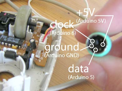
You can measure from the pins on the connector to the wires inside the mouse. Note which is which before you cut the cable. These wires are most likely colour coded, like mine (visible just left of the captions).
The ps/2 protocol is not symmetric. Acting as a device is different from acting as a host. The attached library, ps2dev, implements the device side of the protocol. It can be used to act as a mouse or a keyboard.


